
KICK
The TileV3 is Patent Pending!
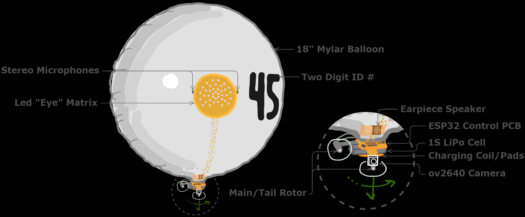
Many of the diagrams in this post came straight out of my application
I spent $65 for 4MB of space on one of the USPTO’s servers (that’s $16,250 per GB). They must store everything in GPU VRAM at that price! In all seriousness, I really did it for the experience and some protection for my idea. I’m not sure anyone else is crazy enough to pursue lighter the air AI assistants but it gives the project some credibility. The new design is very simple because of the stringent weight constraints I go over later. I decided to make it neutrally buoyant to make the 120mAh battery last as long as possible. I hope my PCB efforts saved enough weight for me to add another motor but my current plan just uses two 0408 motors. From testing I could make basic forward movements with this configuration but air currents make this less reliable. I’ll be able to counteract vertical air currents easily but I’d need a third motor to have any hope of staying still in a drafty room. I enjoy the engineering challenge of this project and I’m excited to get the Tv3 talking either way.
New Tile, New PCBs!
Much Lighter then Official Modules!
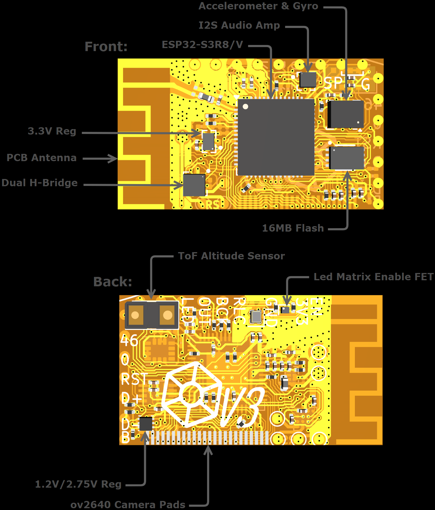
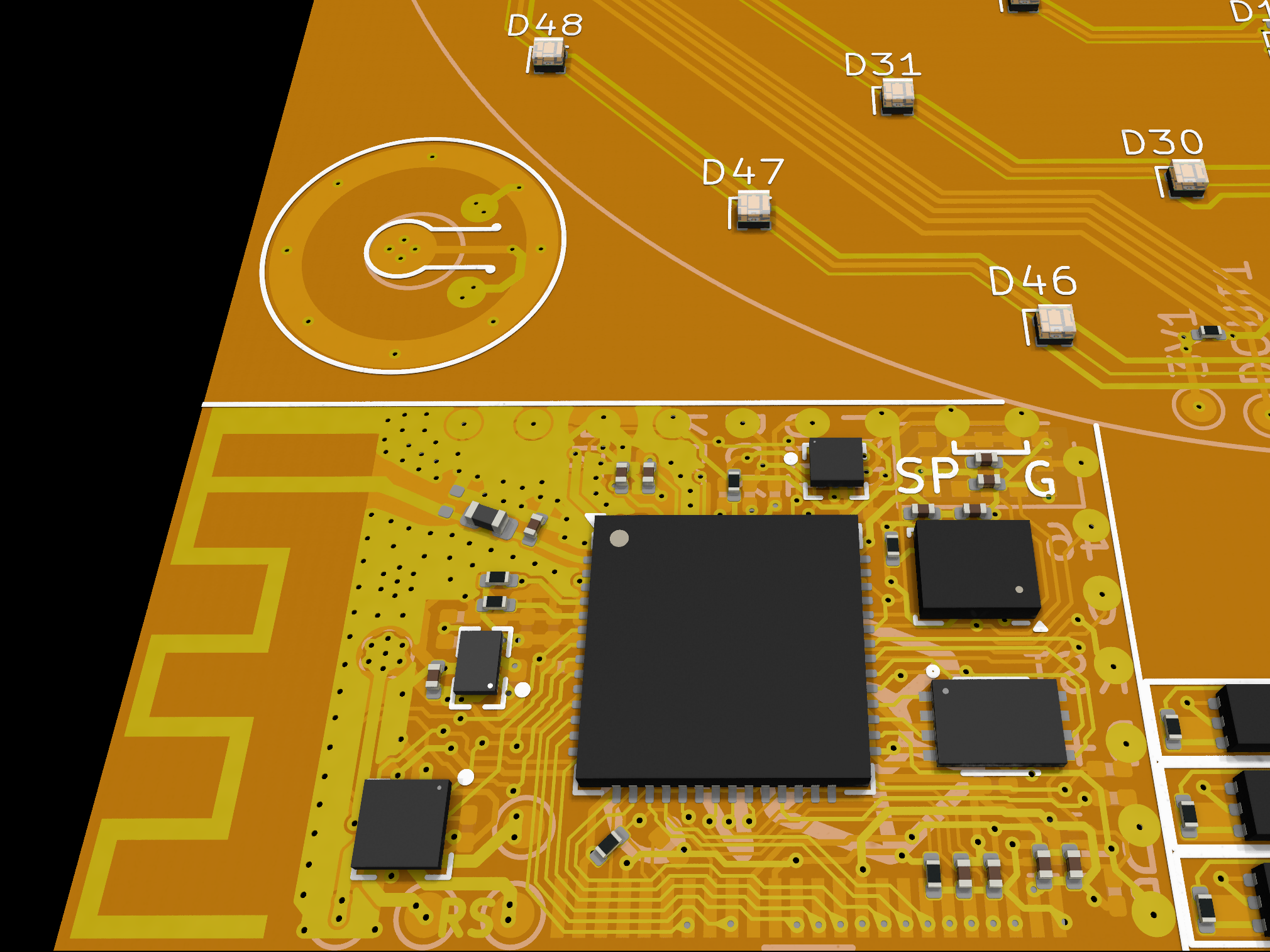
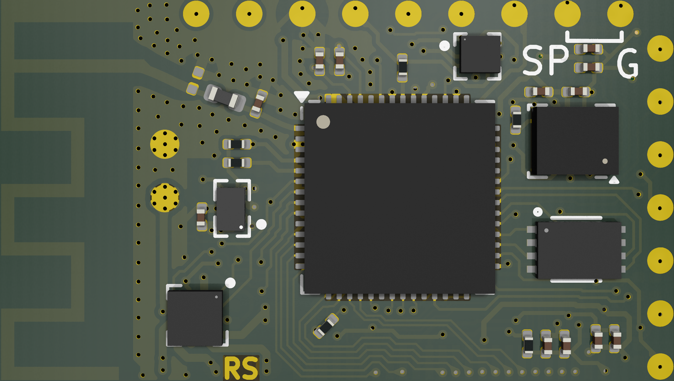
The main TV3 PCB is only 25.3 x 14.4mm (2 layer!) but packs a full AI robot’s worth of functionality. I designed the board to be compatible with the S3R8 and S3R8V (EOL but in supply and cheaper) to help with supply issues. This was my first design to deal with antennas and impedance matching. I calculated the trace width using KiCAD’s built in calculator tool and came up with ~0.37mm for the 50 ohm feed trace (based on JLCPCB’s FPC specs). I used a standard Texas instruments PCB antenna for simplicity.
I routed all the high speed signals first and then spent days moving traces until everything fit in. Admittedly I made some compromises to hit this ambitious form factor. The switching regulator and dual H-bridge are fairly close to the antenna and I had to use 0.08mm camera traces. I made sure to include plenty of vias and the components are very close to the ESP32 to limit long runs.
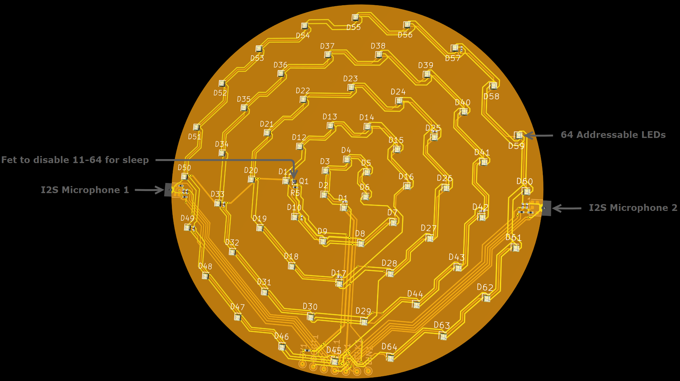
The new LED “eye” board uses addressable 1010 sized LEDs for minimal weight. I also manually routed GND instead of using fills to further lighten this board. I made the microphones hang over the edge of the board to increase separation and to make covering the display possible. During my research I found out that the LEDs have a leakage current that could consume more power then the esp32 in sleep (If I trust the number in the poorly translated datasheet). I included a FET to turn off LEDs I don’t need to make my “Idle” expression. Time will tell if the power save is worth it.
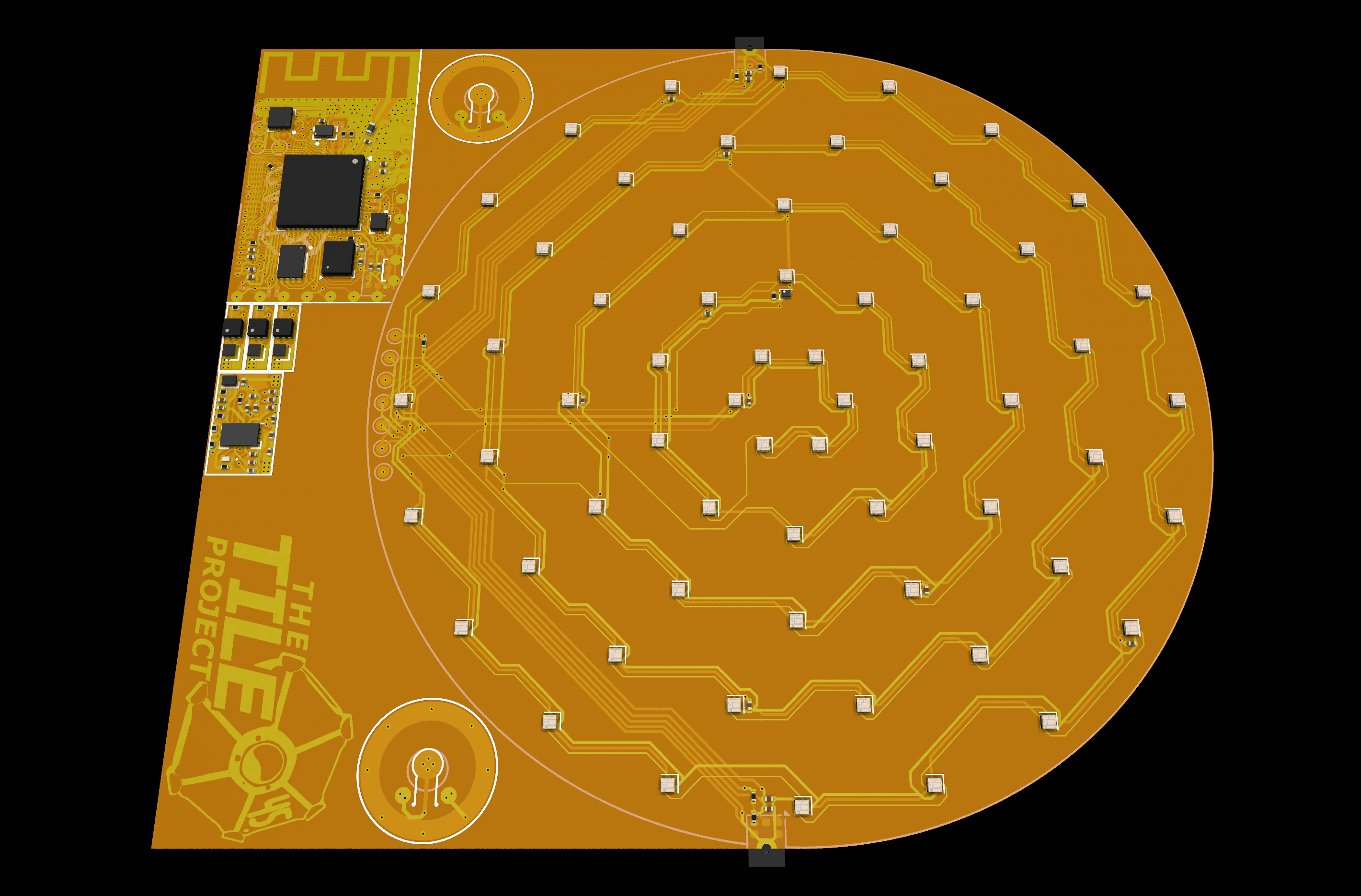
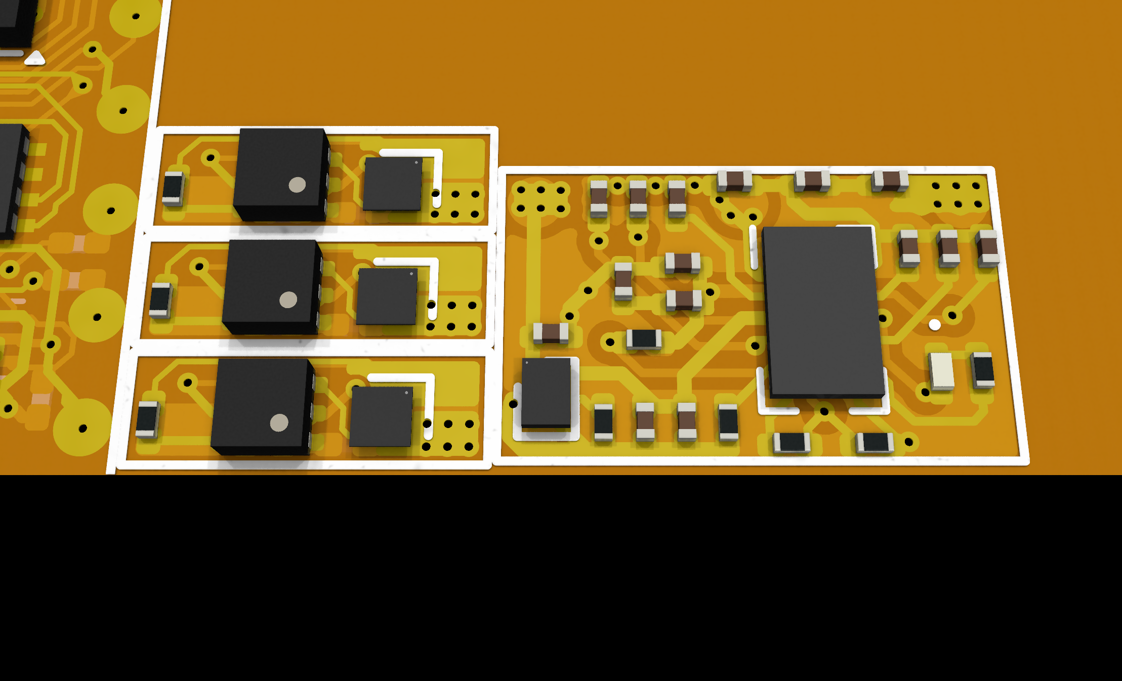
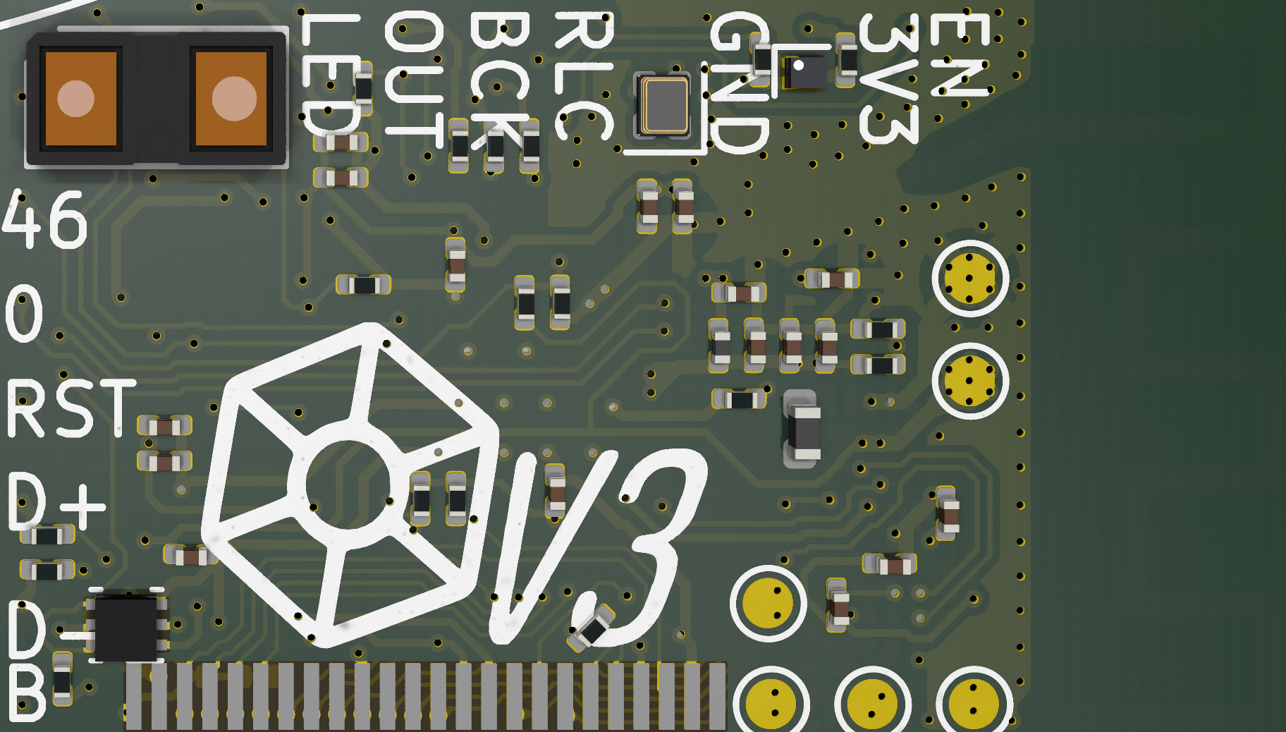
Lastly you can see the 1S battery management system board and wireless charging board I made in the image gallery below. I also included a full picture of the PCB because I ordered all the PCBs on a single board to save cost (it was 1/3 the price and I can just cut the boards apart after assembly).

It's Light Work!
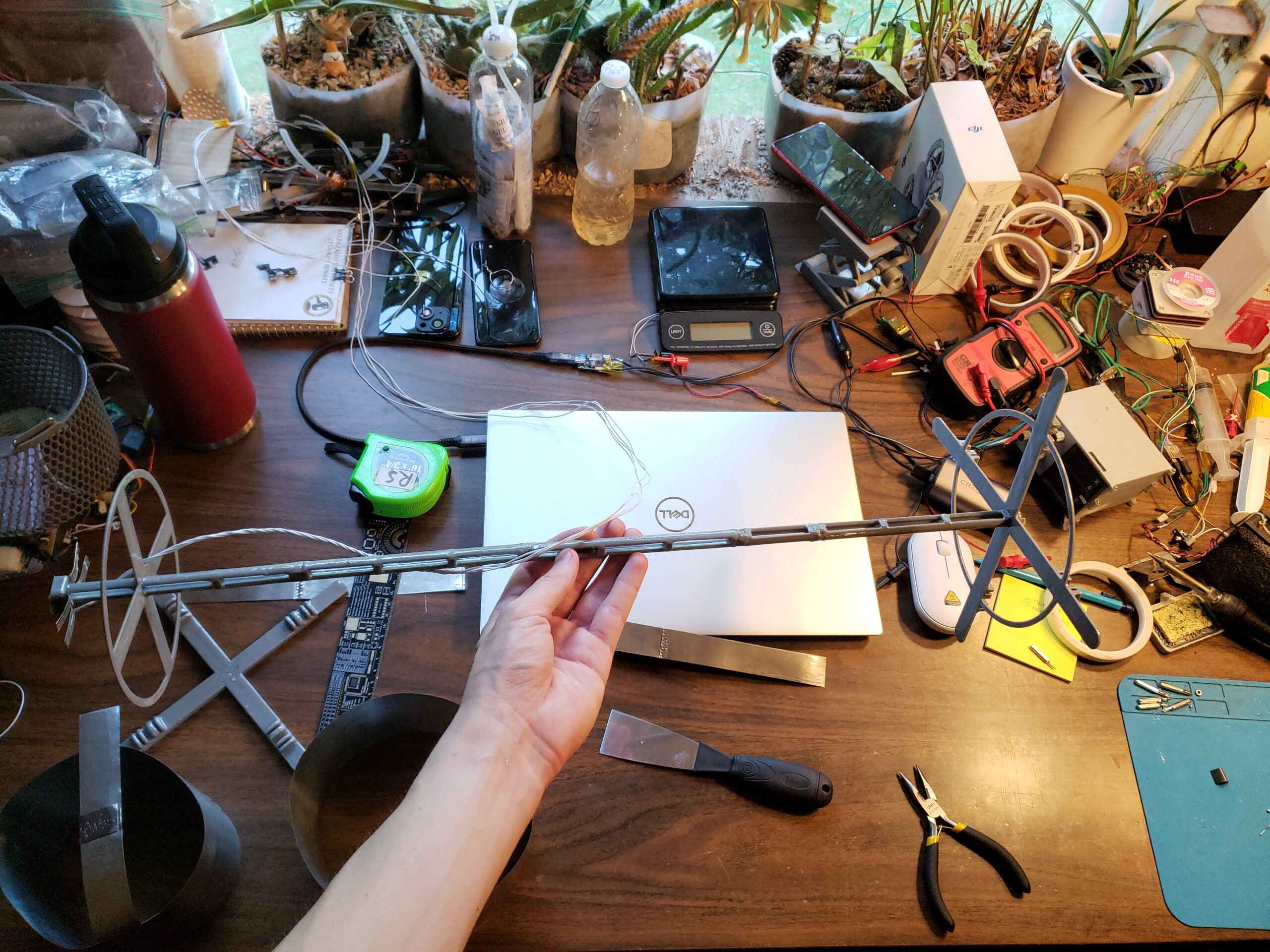
Testing the weight capacity of the 18″ balloon
The weight requirements are very unforgiving because the lift reduces over time. I can get most of the lift back by topping up the balloon every 2-3 days but I’ll eventually accumulate oxygen. These balloons are meant to be disposable so they are much harder to deflate then to top off. I hope to reduce the issue by making the robot as light as possible. From basic testing I found the balloon’s nominal lift is ~6.4g. Here is the planned weight breakdown:
ESP32-S3 PCB = 0.3g
Mic/LED matrix = 0.4g
120mAh/BMS = 2.5g
Wireless CHGR = 0.3g
ov2640 Camera = 0.5g
2×0408/props = 0.8g
Wiring/Tape = 0.2g
Earpiece Speaker = 0.3g
Total : 5.4g!
So based on this estimate, I should have about a gram to spare for lift changes or additional motors. Rooms with different temperatures will effect the robot which might cause the lift motor to run more and waste power. I’ll likely need to manually tune the neutral buoyancy (small rubber bands?) and have the tile tell me when the motor runs too much.
More Hydroysis Reactor Issues
A failed rebuild when I should’ve just replaced the electrolyte
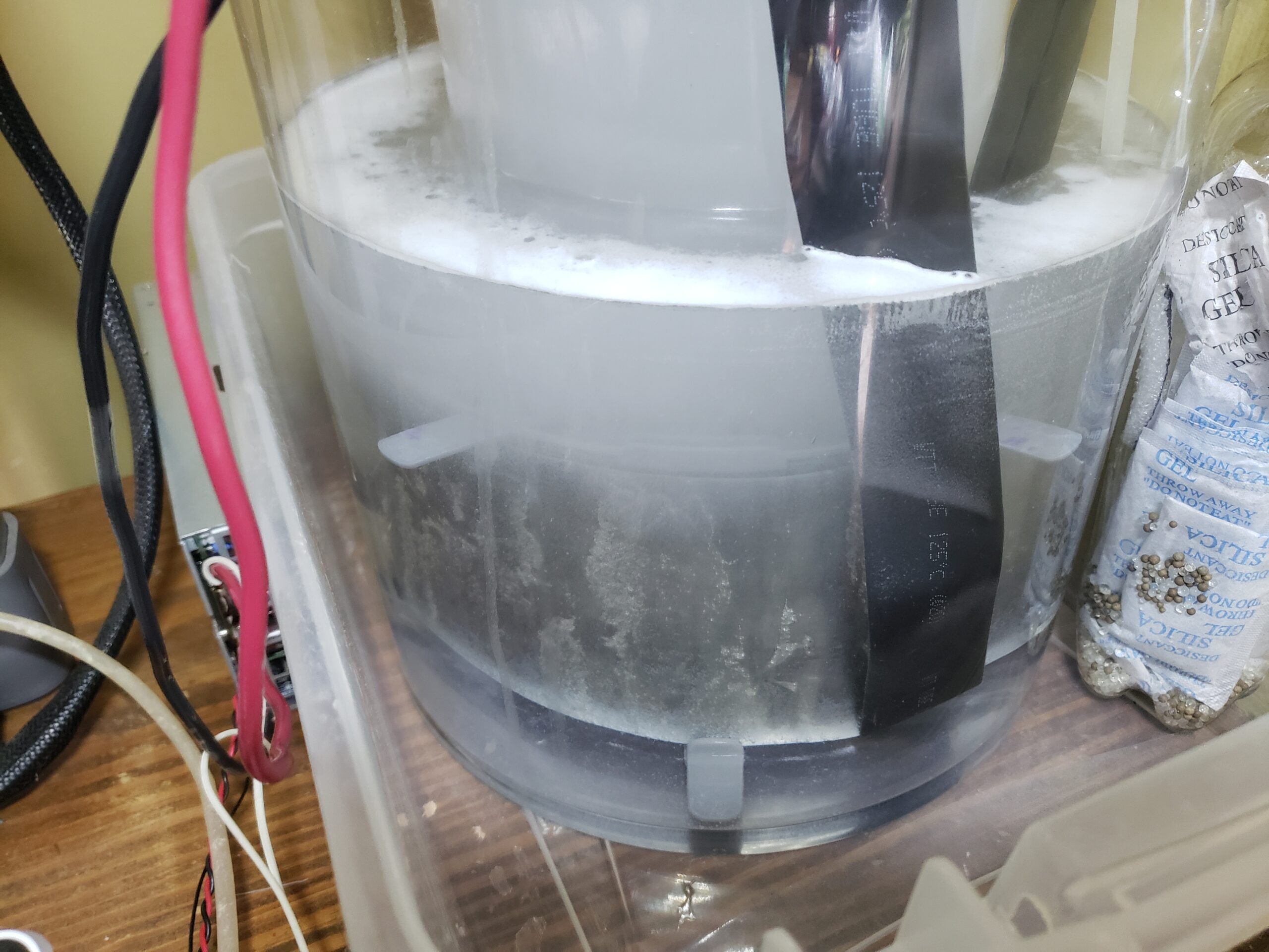
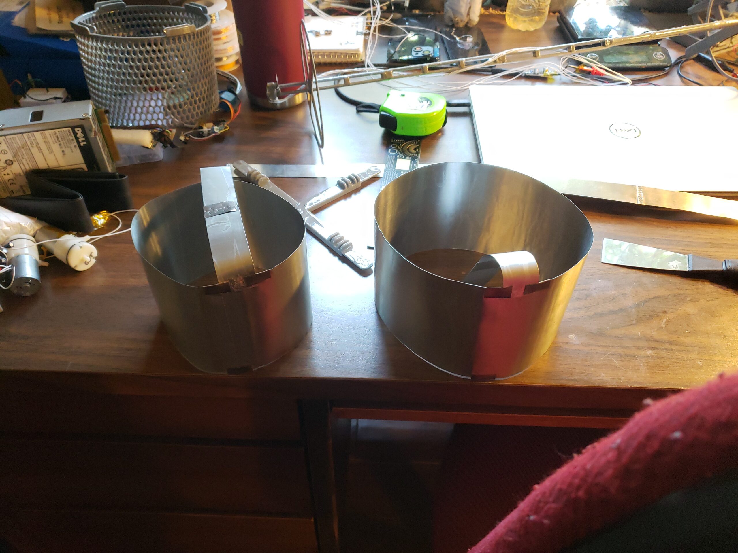
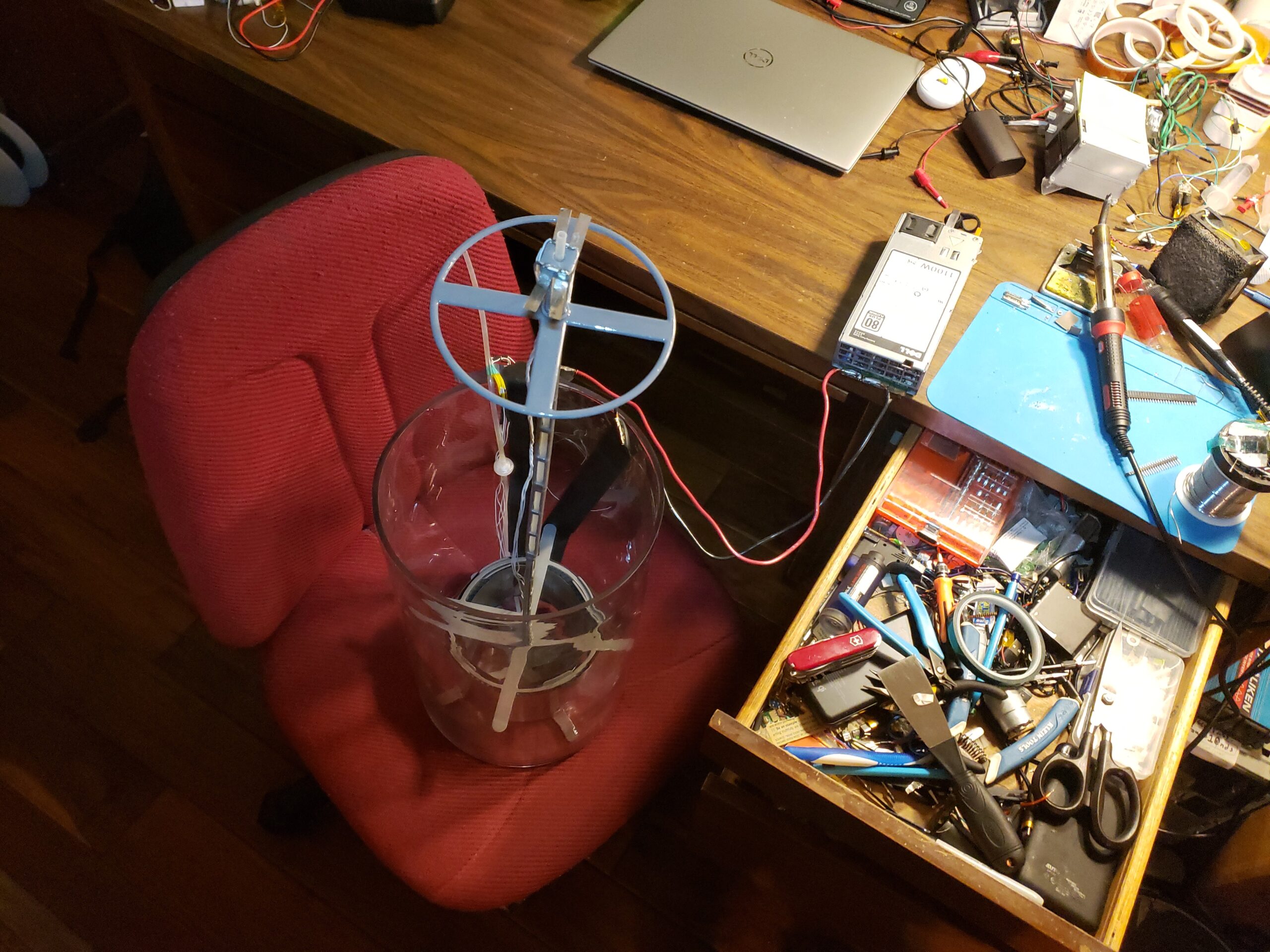
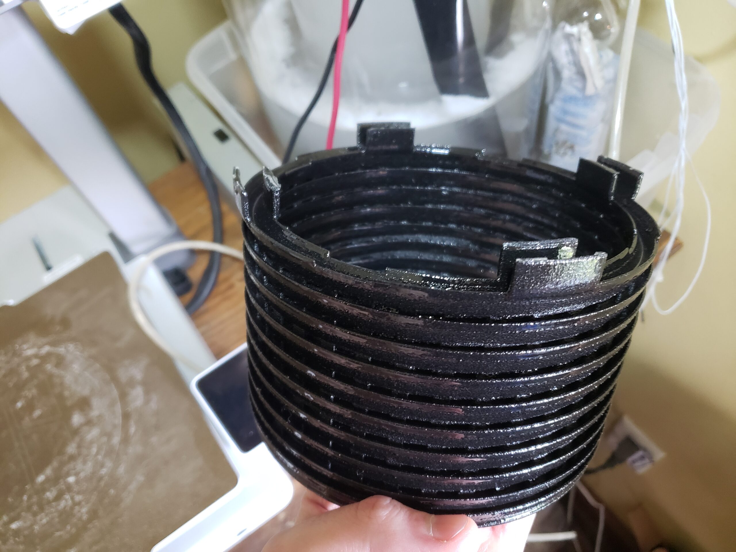
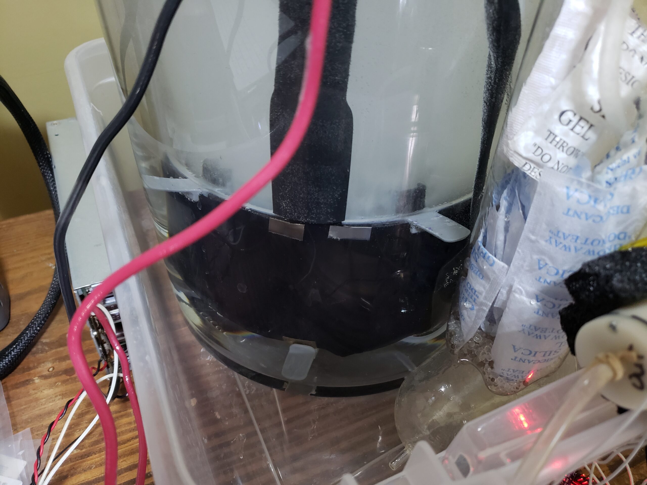
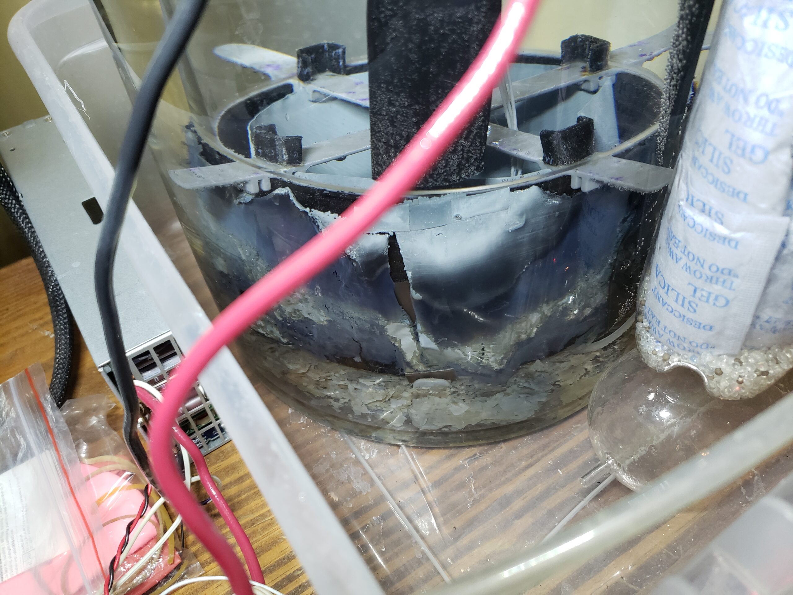
I realized that I bought nickel-plated steel instead of pure nickel for the H2V4 and the cell started producing irritating gas during operation. I got rid of the nickel plates and ordered what I though was pure nickel for a rebuild. Turns out that the nickel steel likely wasn’t the issue and I just needed to refresh the electrolyte. The new plates I got in were thinner at 0.1mm but they weren’t magnetic like the steel was so I gave it a shot (nickel shouldn’t be magnetic). I didn’t add much NaOH so the reaction was slower but it did work for a time. The plates turned dark black during electrolysis (maybe NiOOH?). Eventually I came home to the plates being eaten away during electrolysis. I think the plates were nickel plated aluminium and eventually the outer nickel got compromised.
I’m working toward making this design less hazardous and longer lasting. The nickel-steel lasted for a long time and was likely only limited by the electrolyte going bad. The nickel layer was never compromised (except in an area I deeply scratched) so those plates probably could’ve gone back in. I going to switch to baking soda as my electrolyte because it is much cheaper and safer to handle. The efficiency and speed will take a hit but this doesn’t matter much. The H2V3 was the fastest reactor design because I used a high NaOH concentration. This quickly destroyed the plastic container (with 3-4 epoxy layers!) so I never used this high concentration again. So the slowdown from using NaHCO₃ won’t even be that noticeable and it will be much safer.
Software Progress So Far...
I’m finally dropping Raspberry Pi’s and embracing FreeRTOS
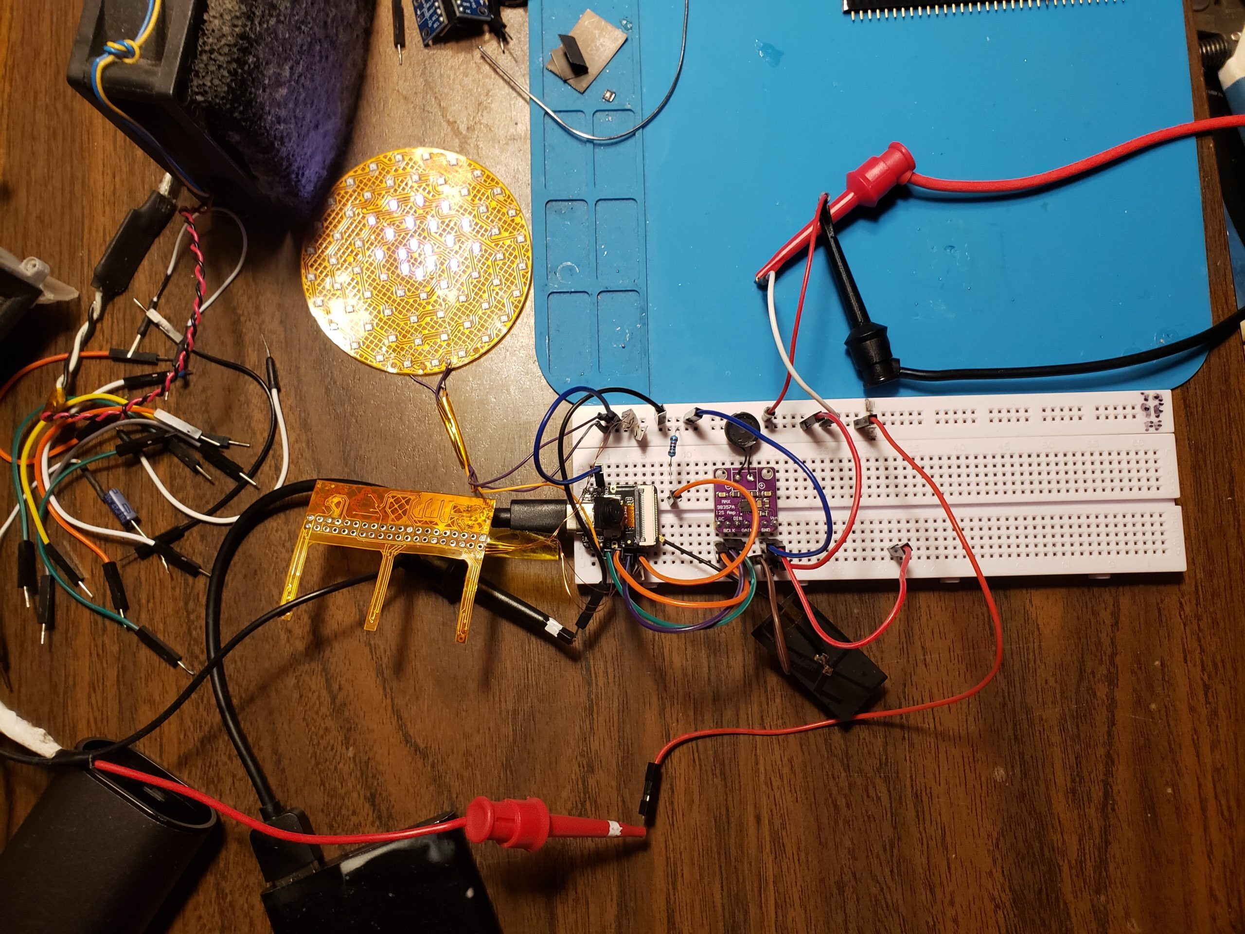
The program loop should be relatively simple but periodic tasks like updating emotions and the sensor/movement loop are best done with task switching. Active mode is the most demanding because it could require emotions, movements, recording, and audio playback at the same time. I haven’t started the FreeRTOS transition yet because I want to test all the hardware first (my breadboard setup doesn’t have the motor driver, MPU, etc). I’m trying to test as much as I can before I get the full hardware.
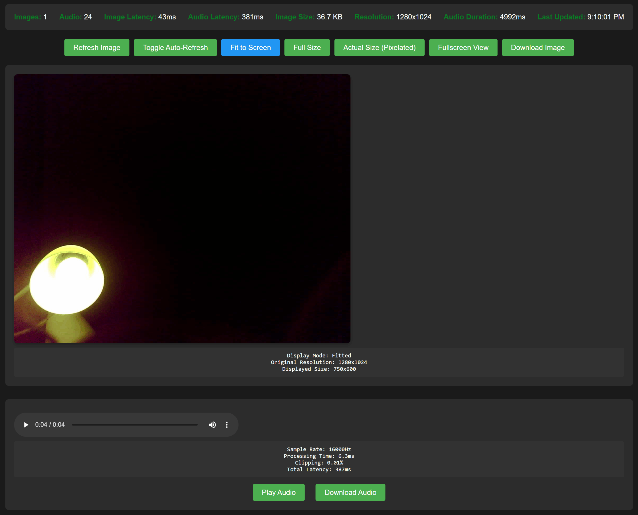
The screenshot above shows a test page hosted by my server. The Esp32 is connected to my server over my Cloudflare Tunnel/domain. It sends a jpeg from the ov2640 camera along with 5 sec of stereo audio. I filter the audio on the server side (high pass, amplification, etc.) and the output is scary good (clear speech from a room away+). I’ll implement a “Hey 45” keyword detection system to avoid constant responses. The camera situation isn’t as good yet. The xaio esp32-S3 Sense board I’m using for testing applies 1.8V to the 1.2V VDD-D rail (their schematics are public) so the camera heats up. I hope the sensor isn’t damaged but it was getting very hot during captures. I’ll do some image filtering on the server side and I have more cameras on the way to hopefully solve this issue.
This Week's Gallery:

Plans Going into the Semester
I wish I could’ve had a prototype to bring in the first day but setbacks with the Hydrolysis cell and the late arrival of the PCB made development difficult. I also spent more time then I should’ve on the last post. I’m excited to finally get back on this project and nothing is going to stop me from getting the Tv3 built soon!
Todo List:
- Fully test the hardware on my PCB
- Transition current hardware testing code base to FreeRTOS
- Assemble the new Hydrolysis cell once I get the plates in