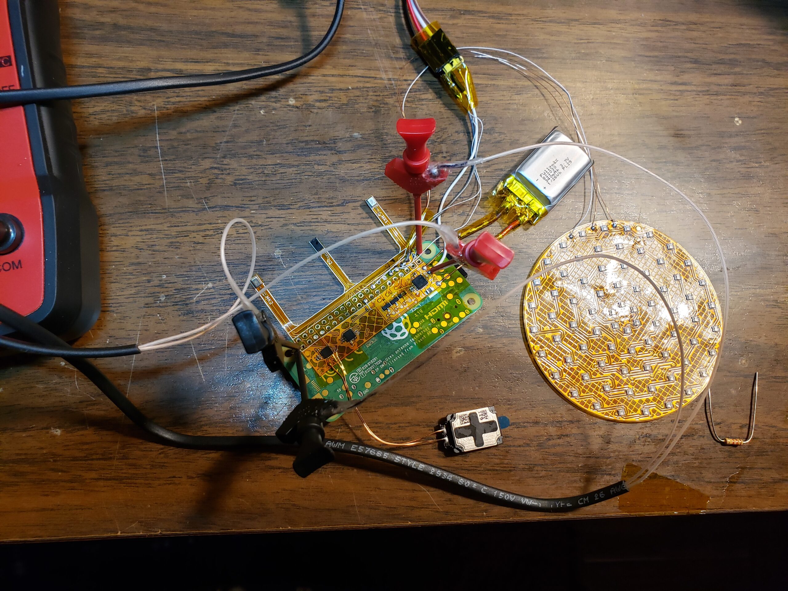
The 5V output from the IP5209 power bank IC shuts off if I don’t draw enough power
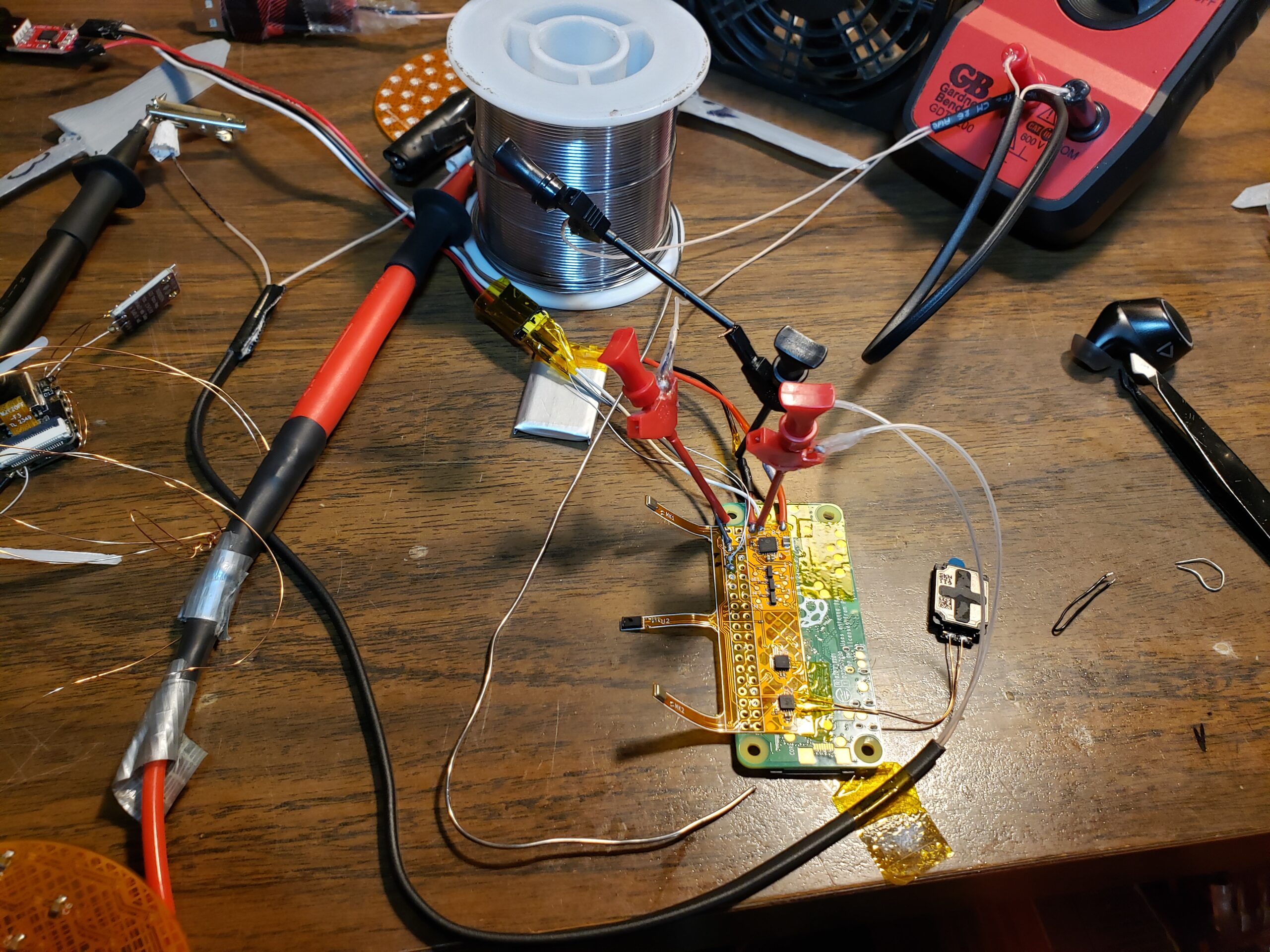
The power bank IC that I’m using was very convenient but I forgot about this annoying protection feature. I can get power to the board though the charging port and if I “press” the power bank key I can get 5V from the battery for a short time. Its enough to fully boot the Pi Zero so my plan is to toggle the pin at some timing to keep the 5V on. I guess this gives 45 an actual heartbeat. So far this has been the only jumper on my board but there will probably be more.
I’m still working out the power situation as of writing but everything else looks promising. I ran an “i2cdetect” and saw the MPU 9250 and the ToF sensor. I’ll also need to test the audio amp and the stereo microphones but that will be for next week. I’m just racing to get something working that meets my original requirements. This circuit will use the same code as the V1 for connecting to the server so development should be quicker. I’ll just need to interface with the new peripherals and *hopefully need to maintain a constant altitude.
All in a Night's Work
You already know I pulled a random all-nighter to get this done
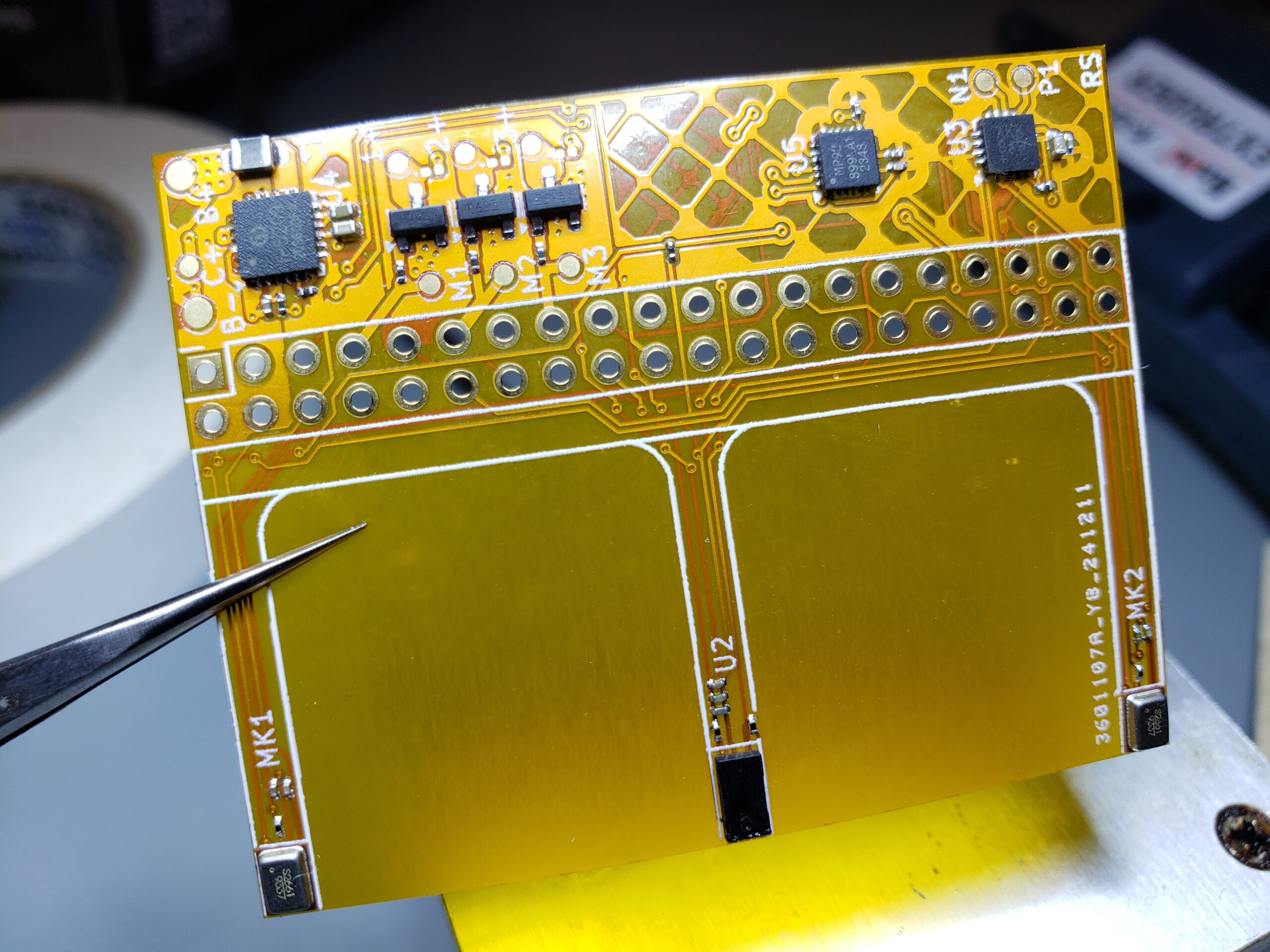
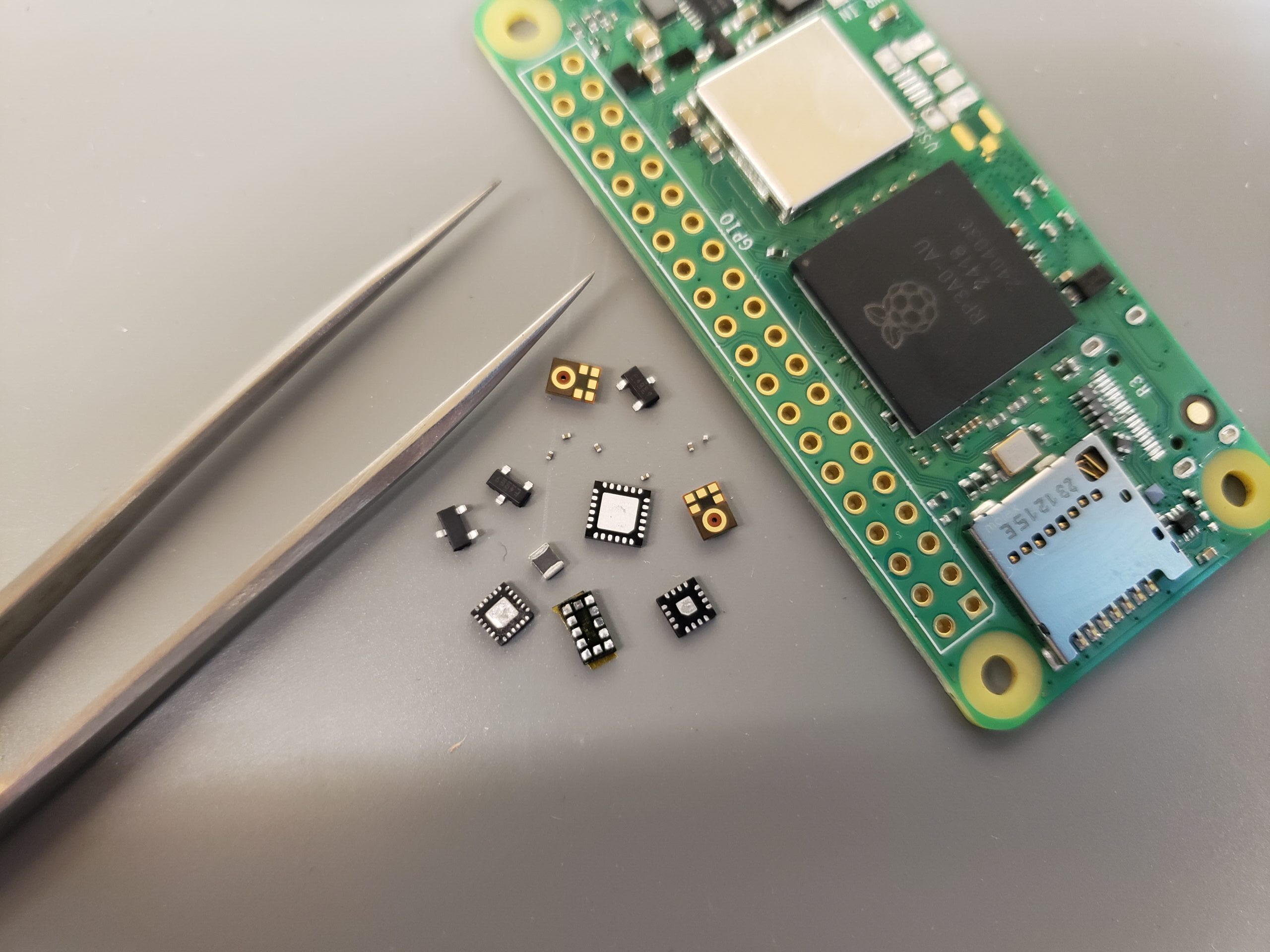
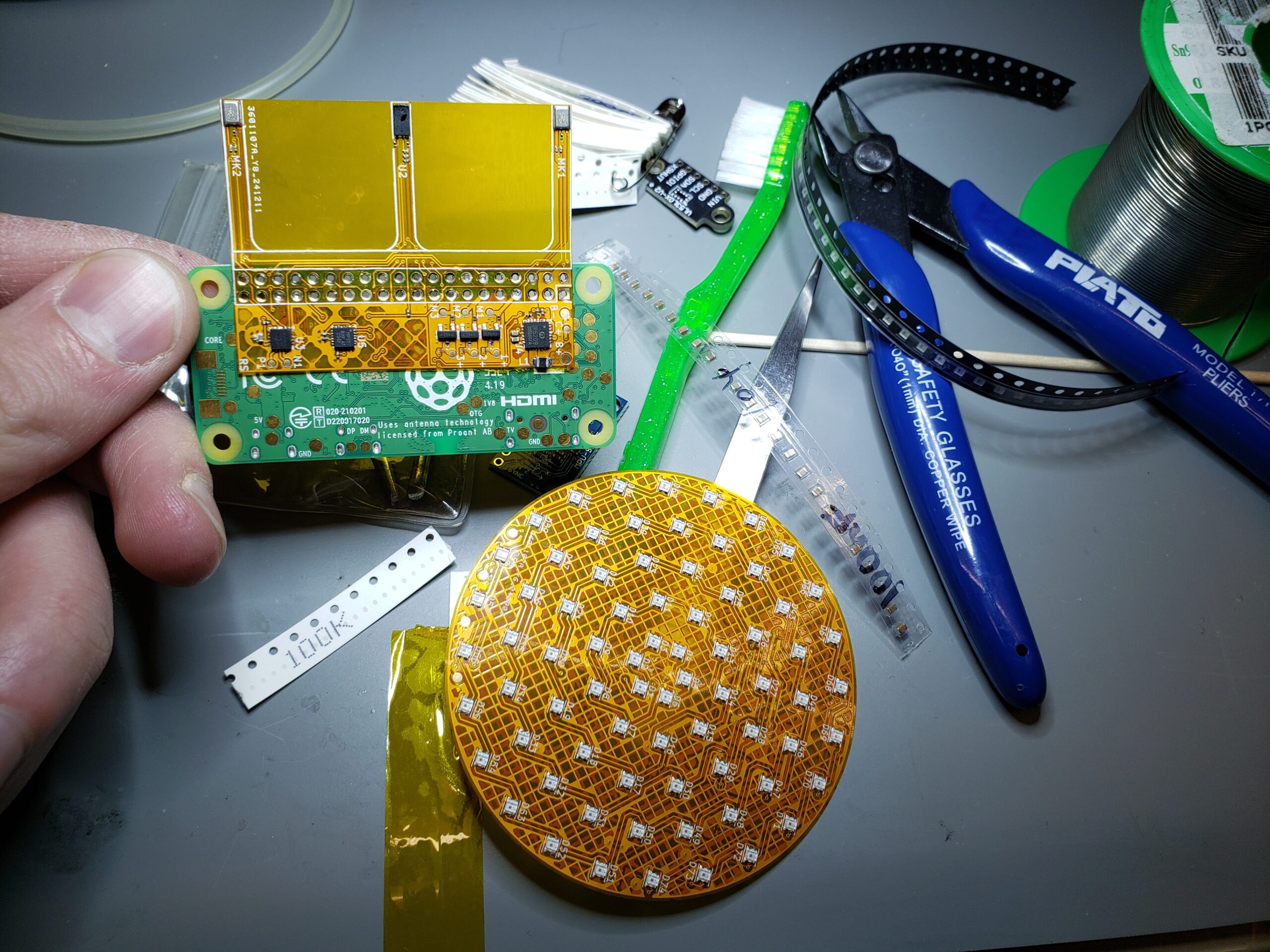
This project is built on all-nighers and this circuit board is no exception. VU has all the tools I need to place and solder all the components so the process was mostly smooth. I couldn’t fix some shorts on the audio amp and I desoldered it once before realizing they were part of the design. The ICs ended up being more trouble then the 0201 components.
I designed the board to use 0201 TVS diodes to act as flyback diodes for the mosfets. I realize this is less then ideal but if I get a diode with a clamping voltage less then 12V and enough current capacity then it should be enough for these slow motors. I realized during assembly that the diodes I chose would clamp the voltage at 32V which was useless for protection. I have some new diodes on the way but my motors don’t turn very fast so it should be ok for now. Overall I don’t see any soldering related issues, just design issues that hopefully can be solved.
This Week's Gallery:
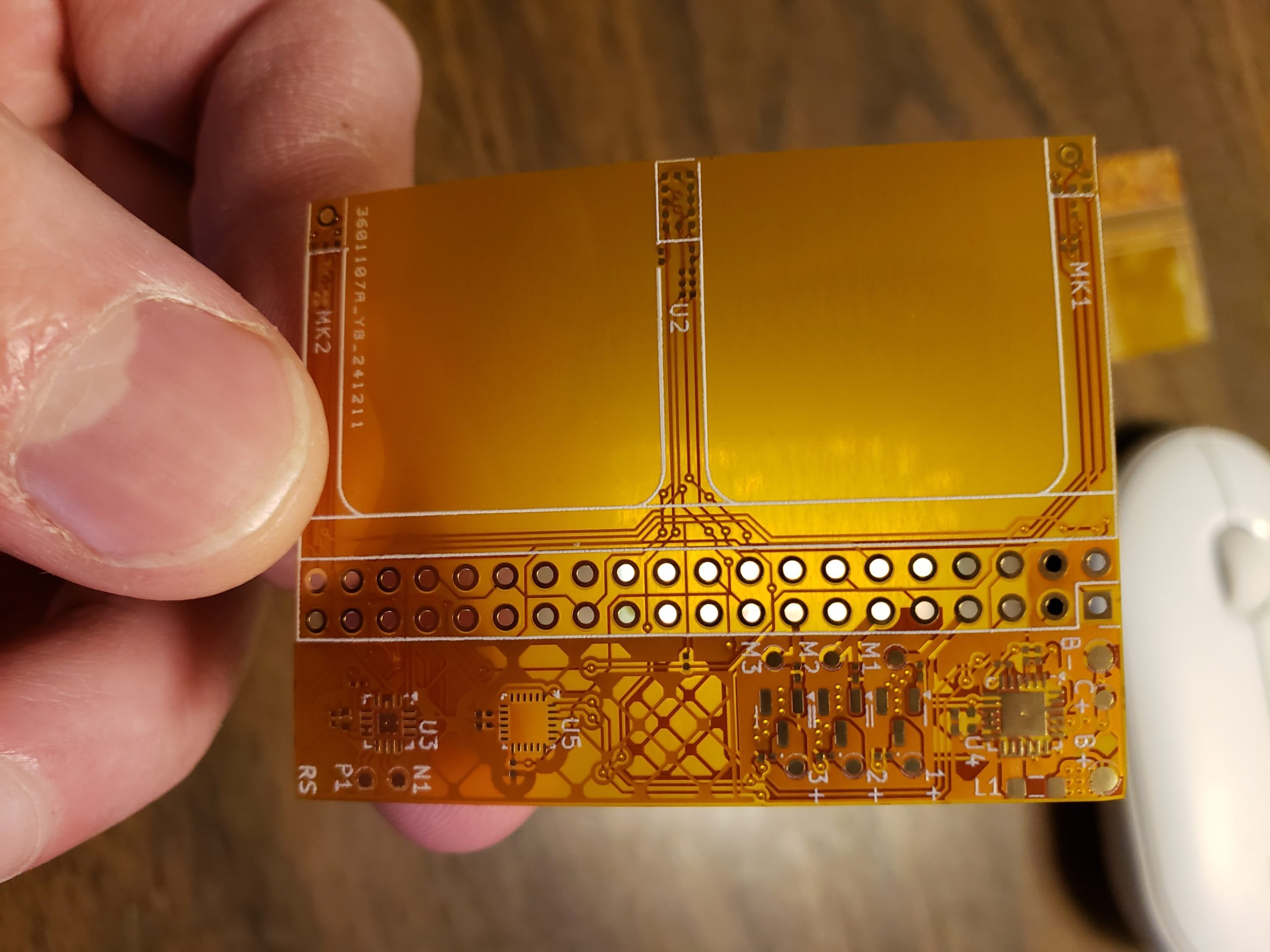
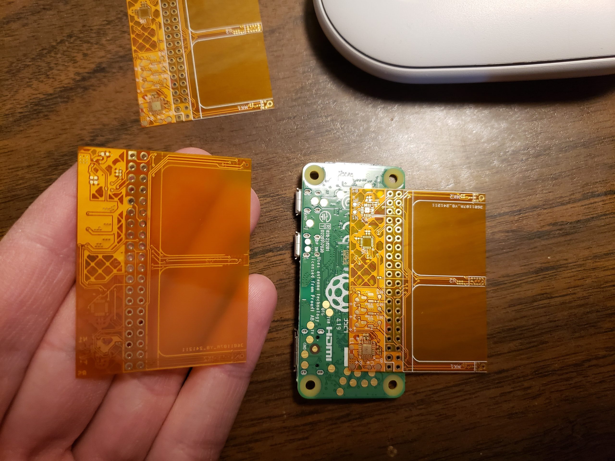
Assembled PCBs ready for testing
Plans For Next Week:
Work out the circuit!
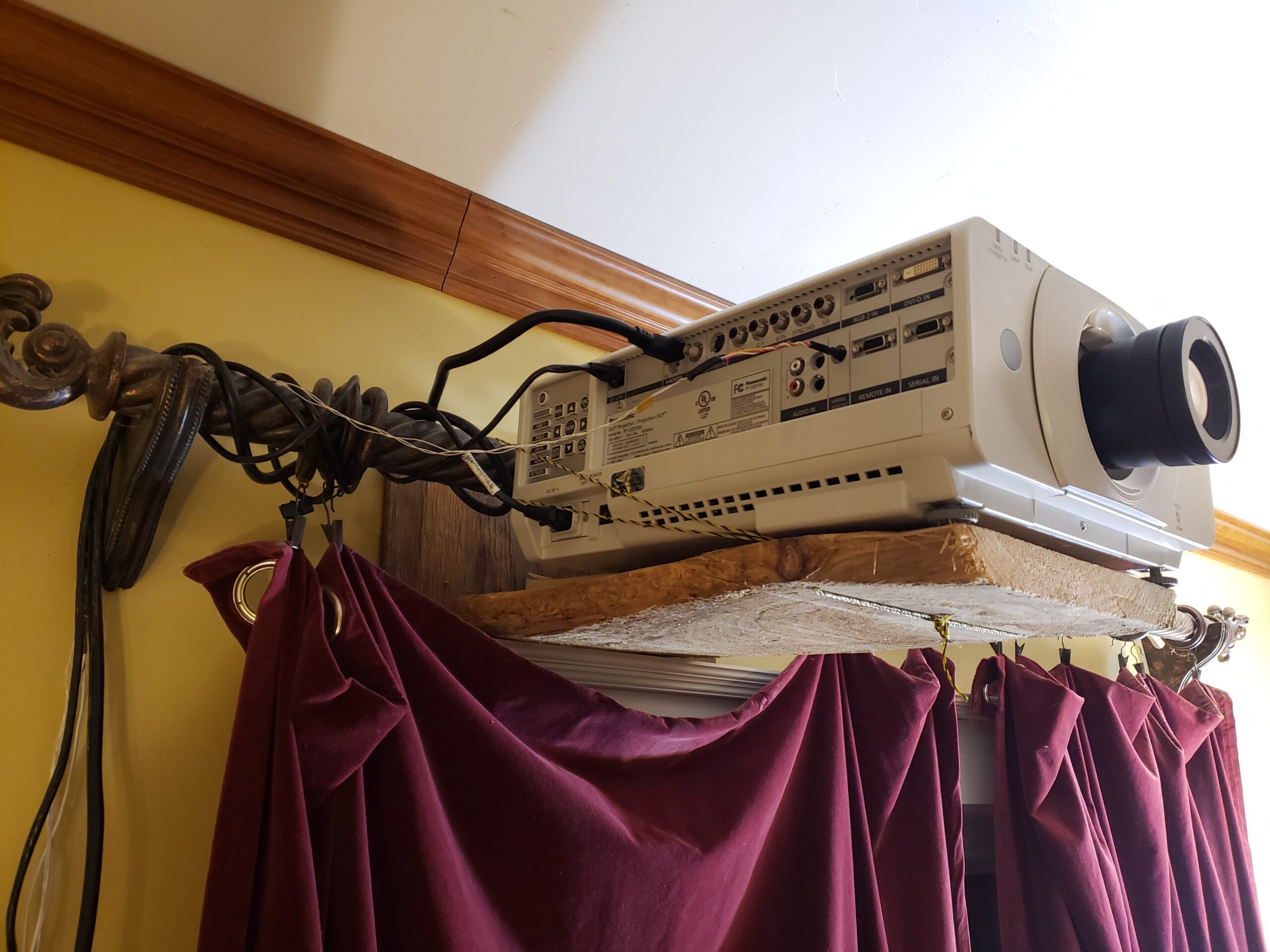
I need to focus on my school’s satellite project a little bit but I still should have time work out the issues with the circuit. I have a few ideas in mind about how to keep the 5V output active but I’ll start with the “heartbeat” method. I also really need to do some CAD to mount the new circuit on the balloon. I also included an image of the Panasonic PT-DZ570U projector I rigged up for my family.