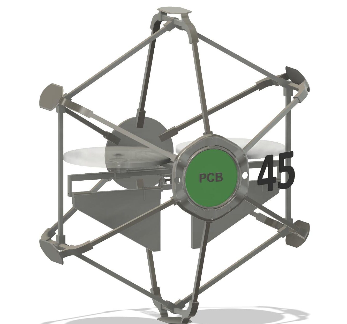
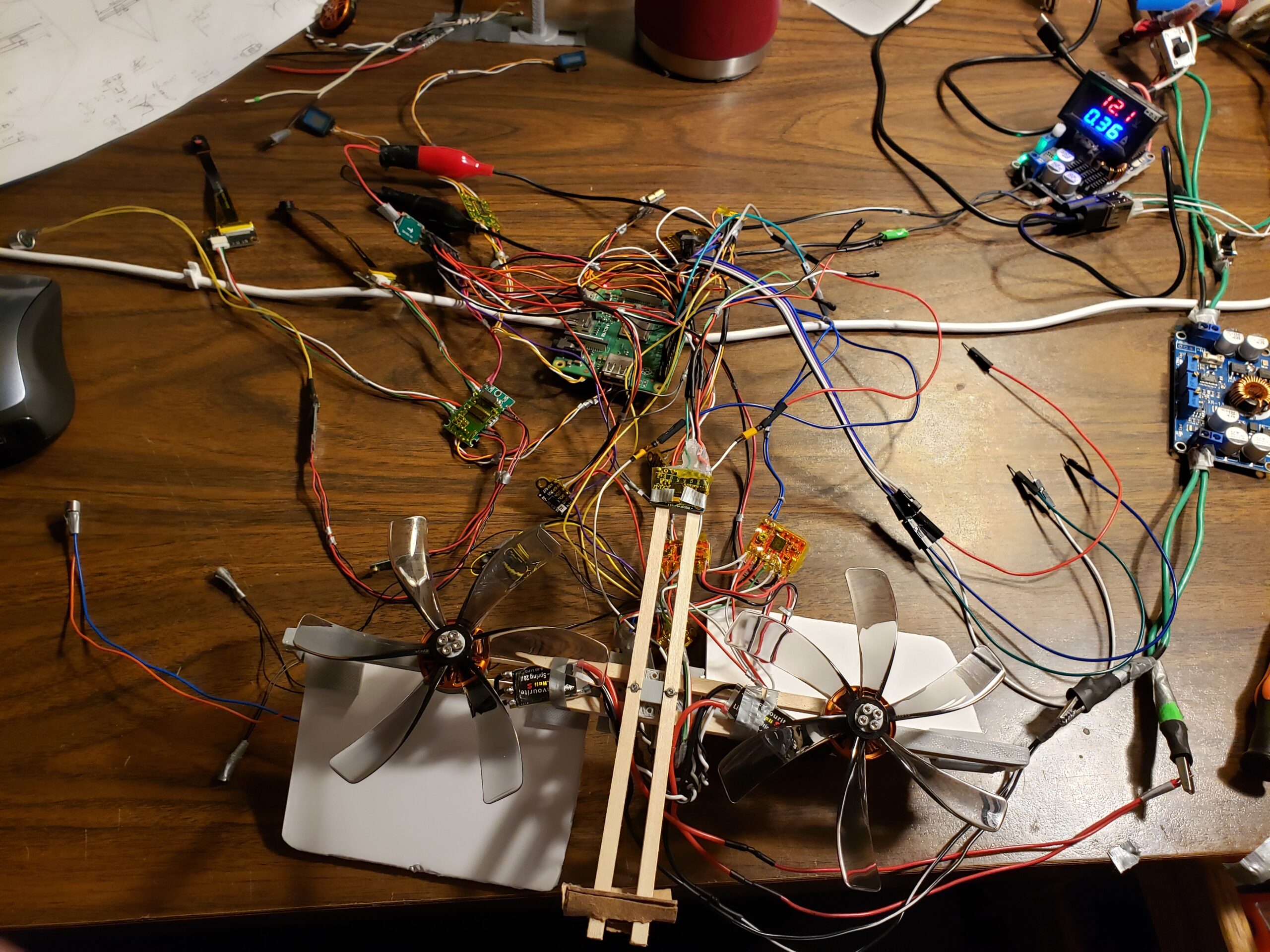
These parts will change but I wanted to see how it all fits together
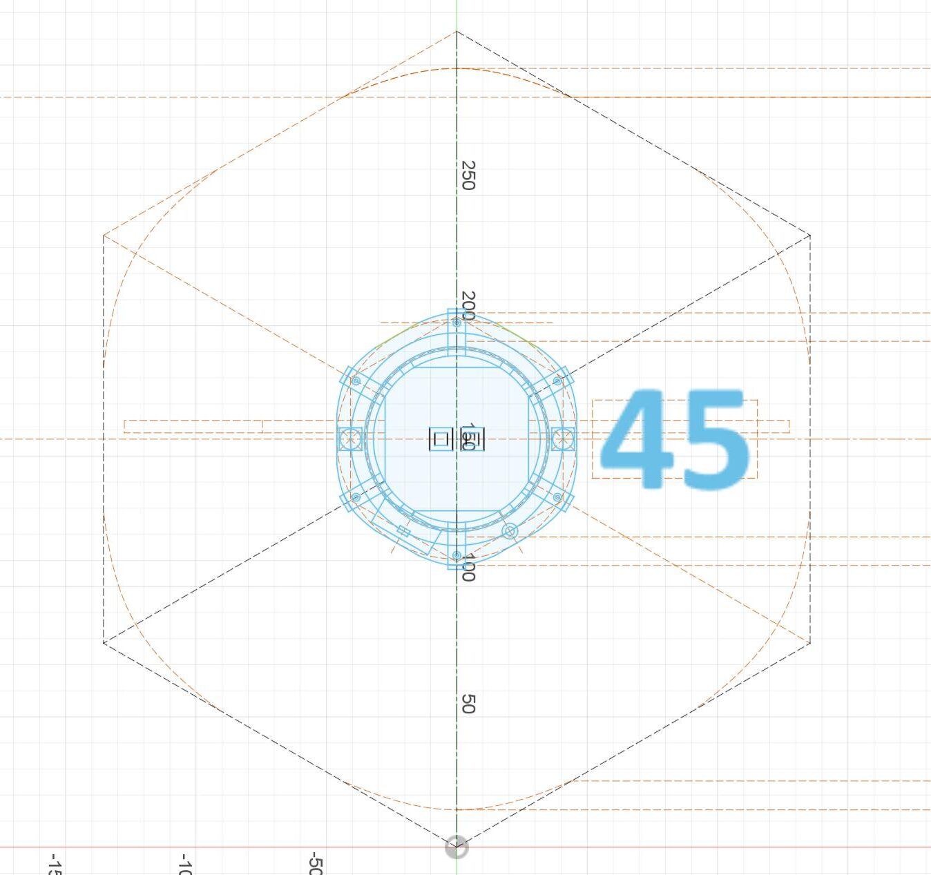
The Model above was made in two days so it is a little rough around the edges. I had to pull two all nighters! to get it ready for this post which didn’t leave me enough time for the demo. The final model will have the foam panels drawn in but I ran out of time. I’ll replace the model above when I have it in a better place. I just wanted to get this post out. These are all self imposed requirements anyway.
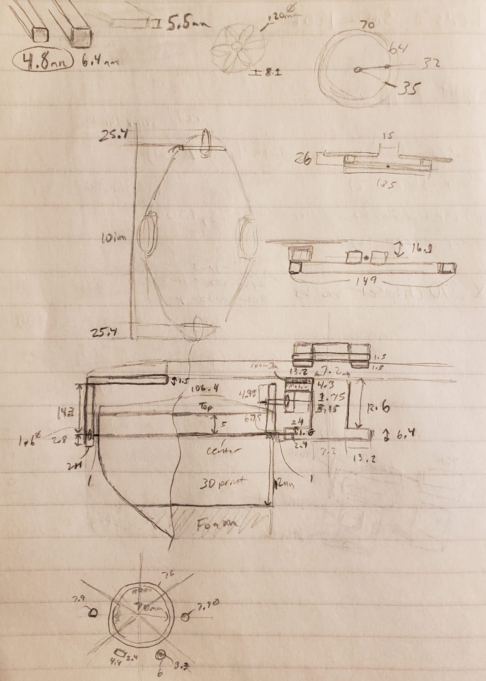
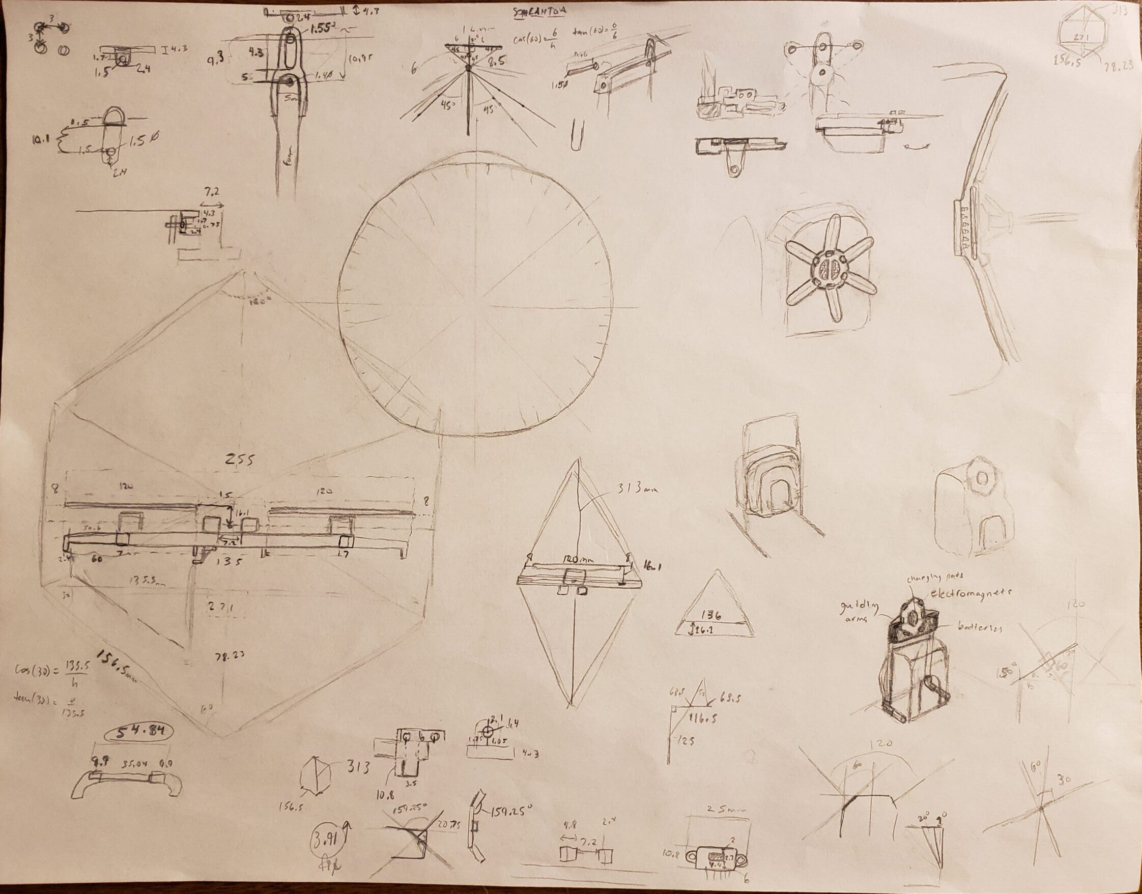
My struggle to design the parts on paper in two days
Trying to visualize the parts was difficult
Now that spring break is over and I’m more time constrained it is difficult to keep pace. I really wanted to have a demo ready for this week but with everything going on I was barely able to get an assembly done. CAD is one of my weaker spots and I found it difficult to visualize how the parts fit together. I originally had all the parts drawn on paper but that became a mess that was prone to error. It became easier after I drew the front and side views in CAD. Once I get a more finalized CAD model with the side panels I’ll replace the render above.
More Less Tolerance!
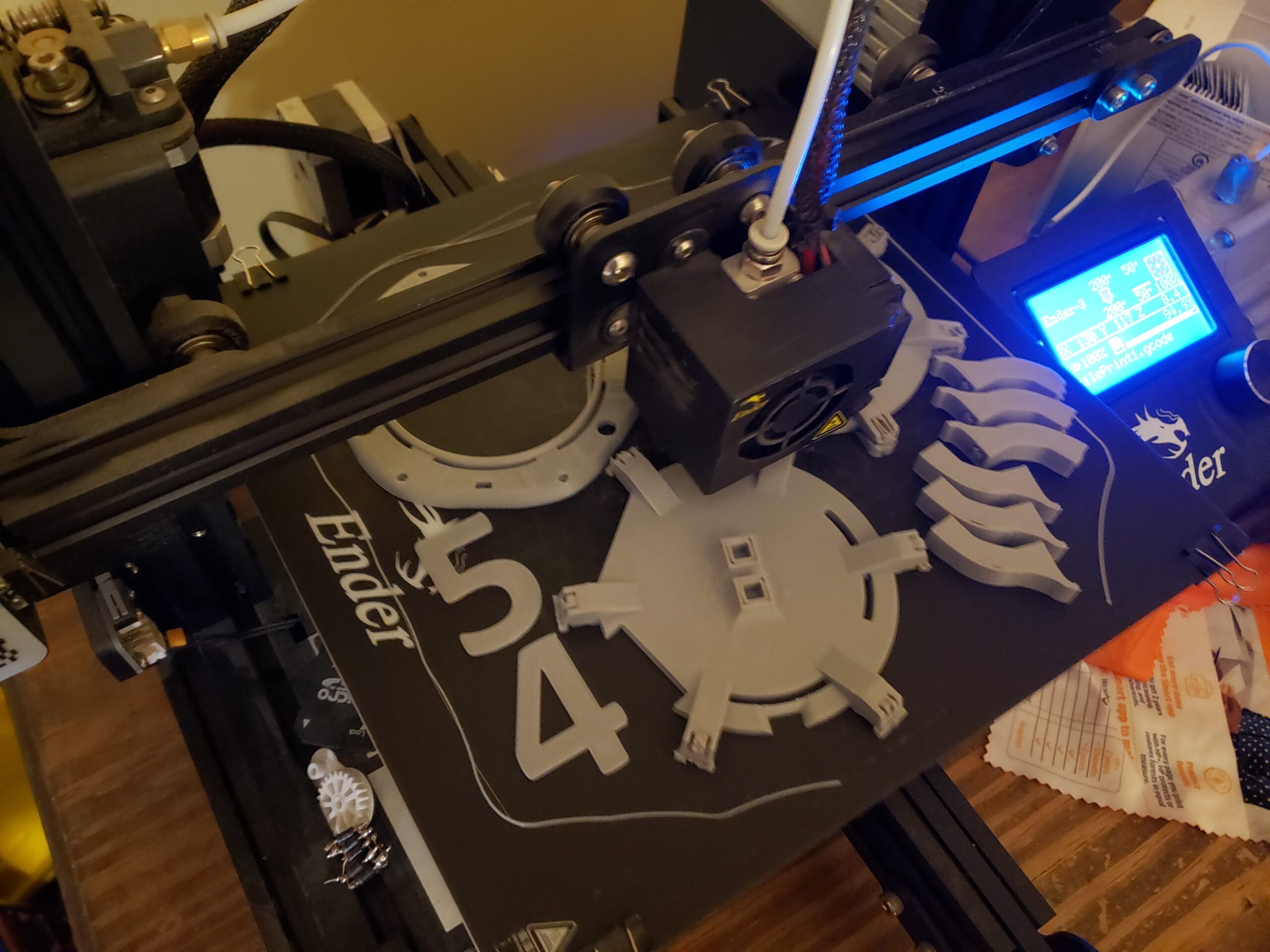
My Ender 3 struggles with the smaller details so design iteration is required
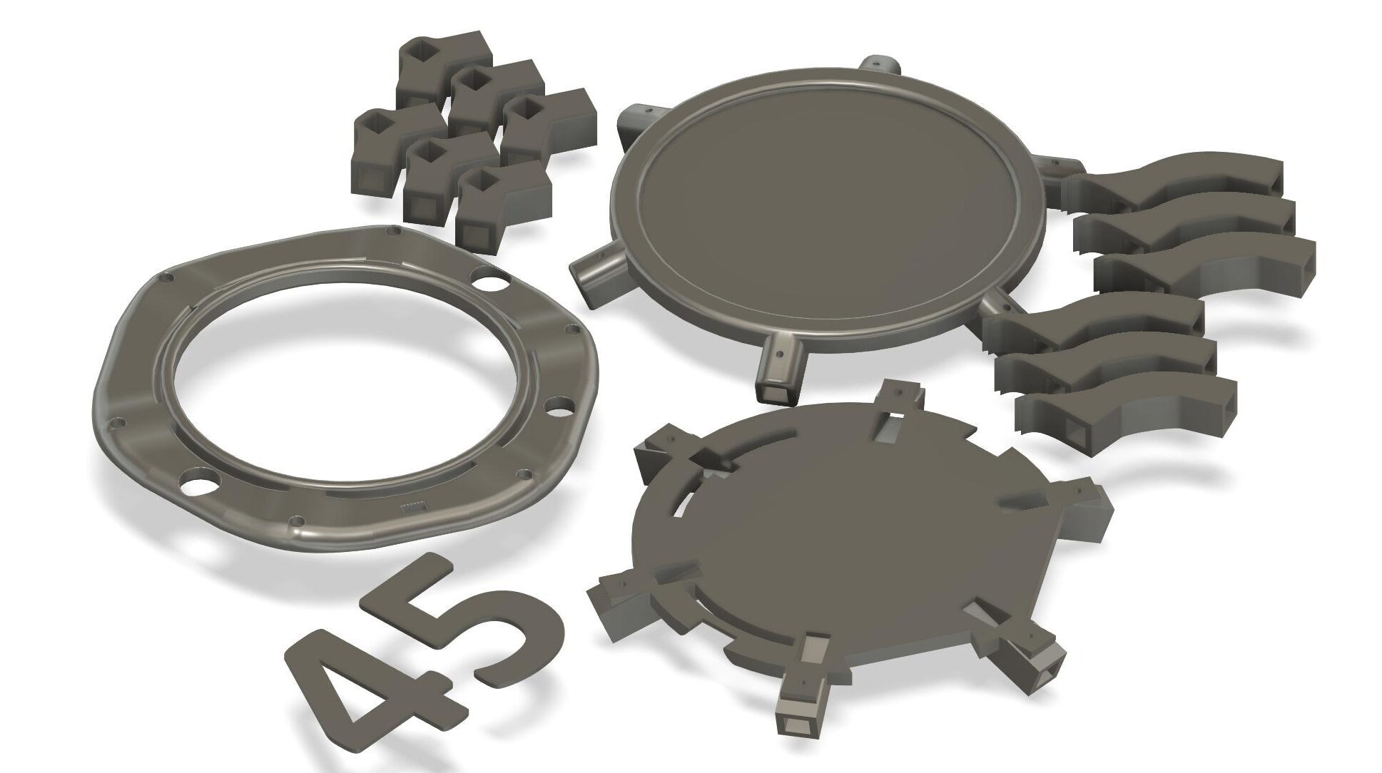
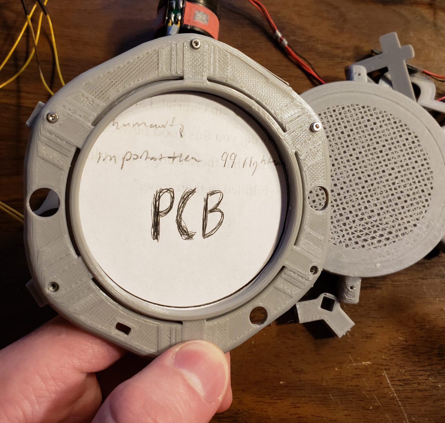
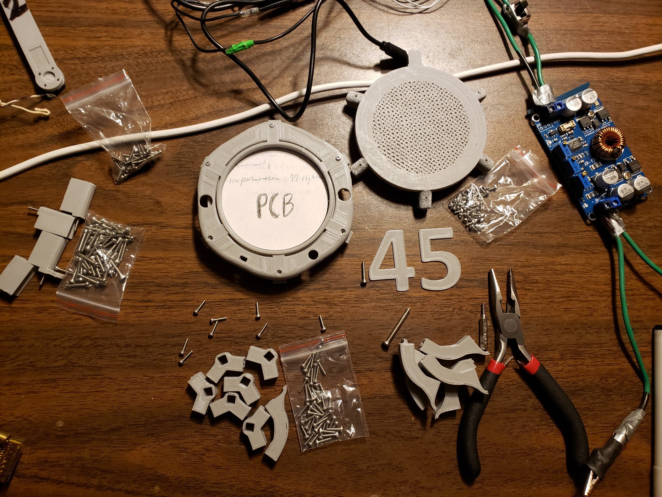
I’ve printed all the parts but there wasn’t enough tolerance so I’ll need to fix them. I purposely left all the parts ugly because I knew that I would need to change them a lot. The angles seem to be correct but my printer over extruded the joints so I cannot fit the balsa wood in them.
I’m still trying to figure out what font I want to use for “45”. I’ll probably end up making my own and tracing it on the front.
It needs to look good at all costs! . . . It will hopefully function too
I tried to add some flare to the face plate but the print turned out poor. I’ll redesign the face place to be larger and I’ll angle the edges to make them flush with the foam panels. I’m shooting for the look in my concept art of course!
The six edges of the tile have built in shock absorbers but PLA tends to be more brittle in my experience. I just printed a holder that I’ll insert other plastic into. These are shown as the six flat parts around the edges of assembly. I’ll redesign the holder so I can friction fit a thin strip of flexible plastic in it. The plastic will bow outward and be covered with an additional foam layer to hopefully absorb drops.
So Where Did The Other 5 Days Go?
I left myself just Fri-Sat to complete that CAD model so what happened to the rest of the week?
I’m back in school so that is a large part of it. I don’t have days to throw at the project anymore. I’m trying to get a demo of this project ready for the final presentation in my Design Process for ECE class but I haven’t told anyone I’m working on this. I’m not sure what I’ll have ready by then so I want the expectations to be zero.
My group’s actual project involves programming an Arduino to act as a clock/stopwatch/timer using a GPS for accurate time. I spent some time doing the programming for that project and I almost have it done. That should free me up to work on this project without feeling guilty.
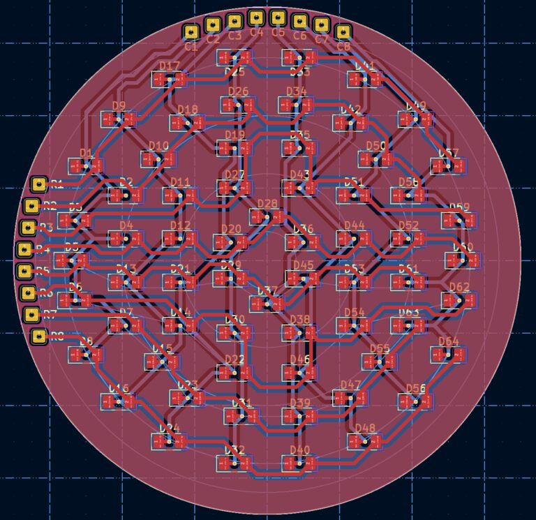
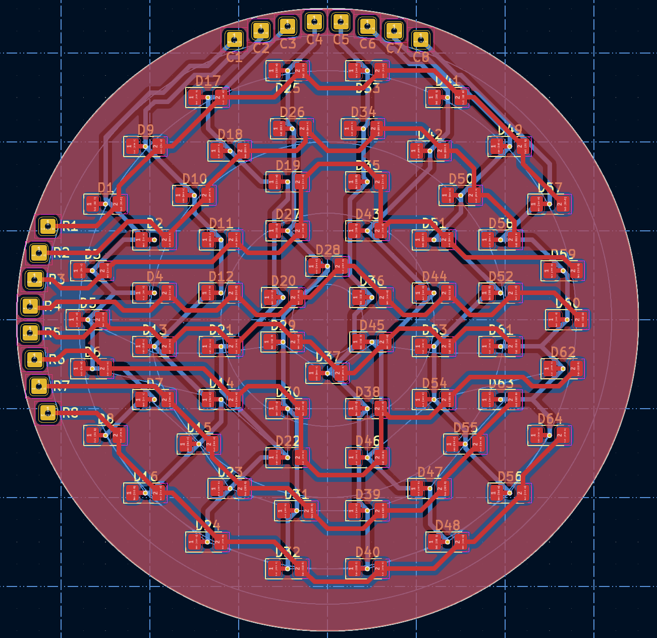
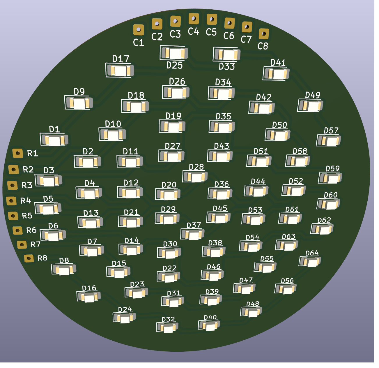
Fixed 70mm Board Layout
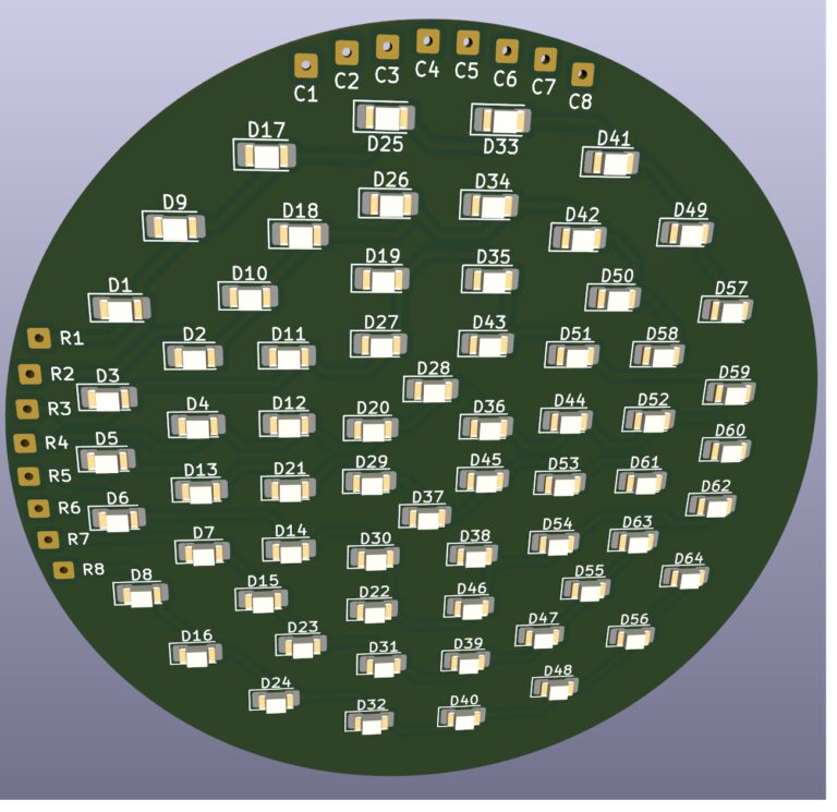
3D Render With LEDs
Oops! That’s not the Radius
I went to order the custom 8*8 matrix circuit board I made and I realized that I accidentally put the diameter in for the radius. I didn’t have the LEDs in back then so I didn’t notice that everything looked too small. Thankfully it didn’t take too much effort to fix the board and finish the order. The LEDs are much closer together now so I’ll need to add a larger diffuser to make sure the emotions are distinguishable from each other.
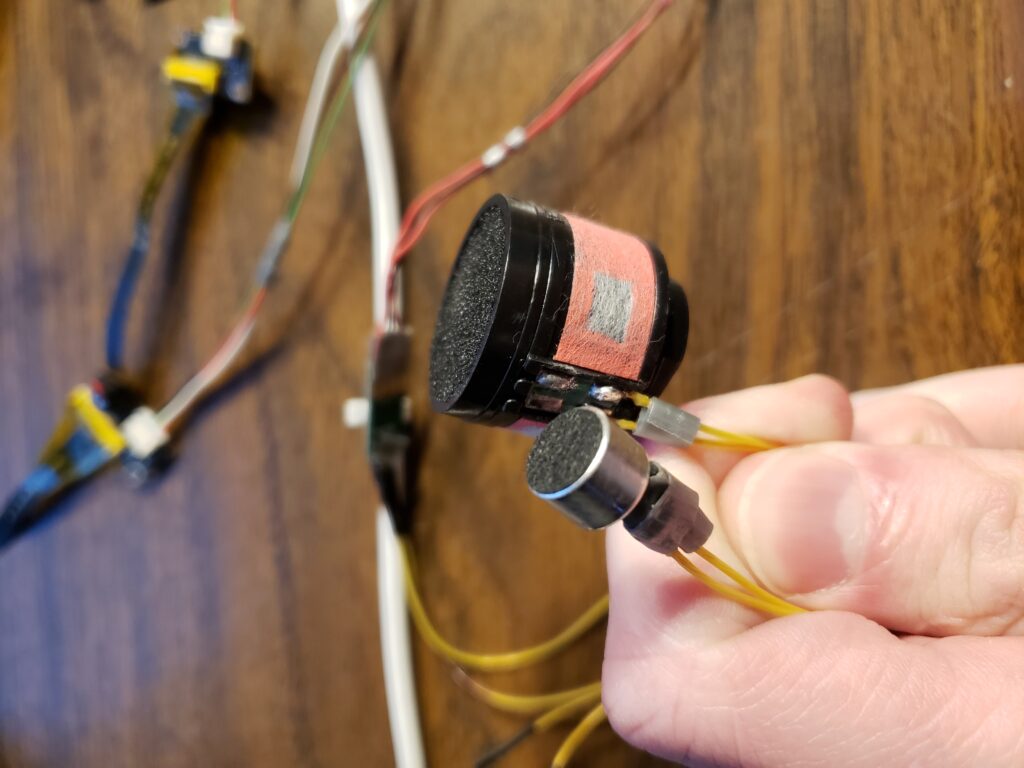
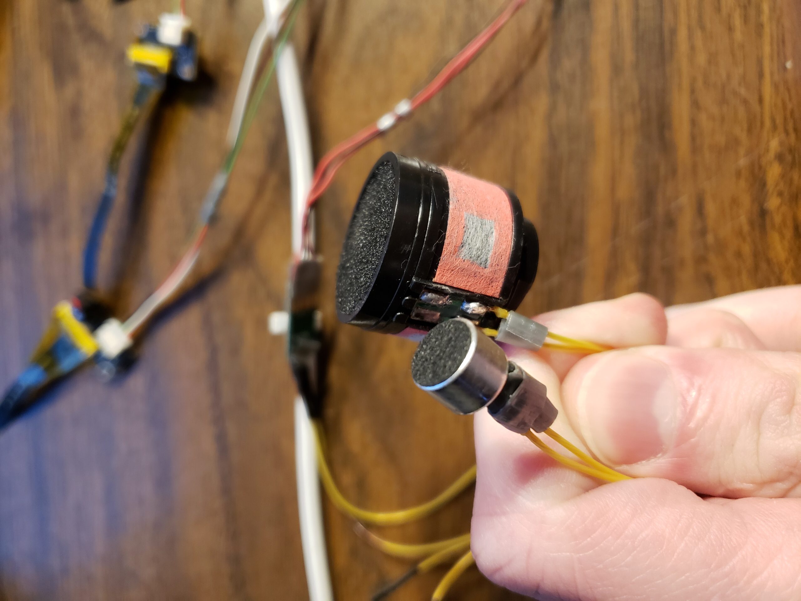
The two other electret microphones I tried
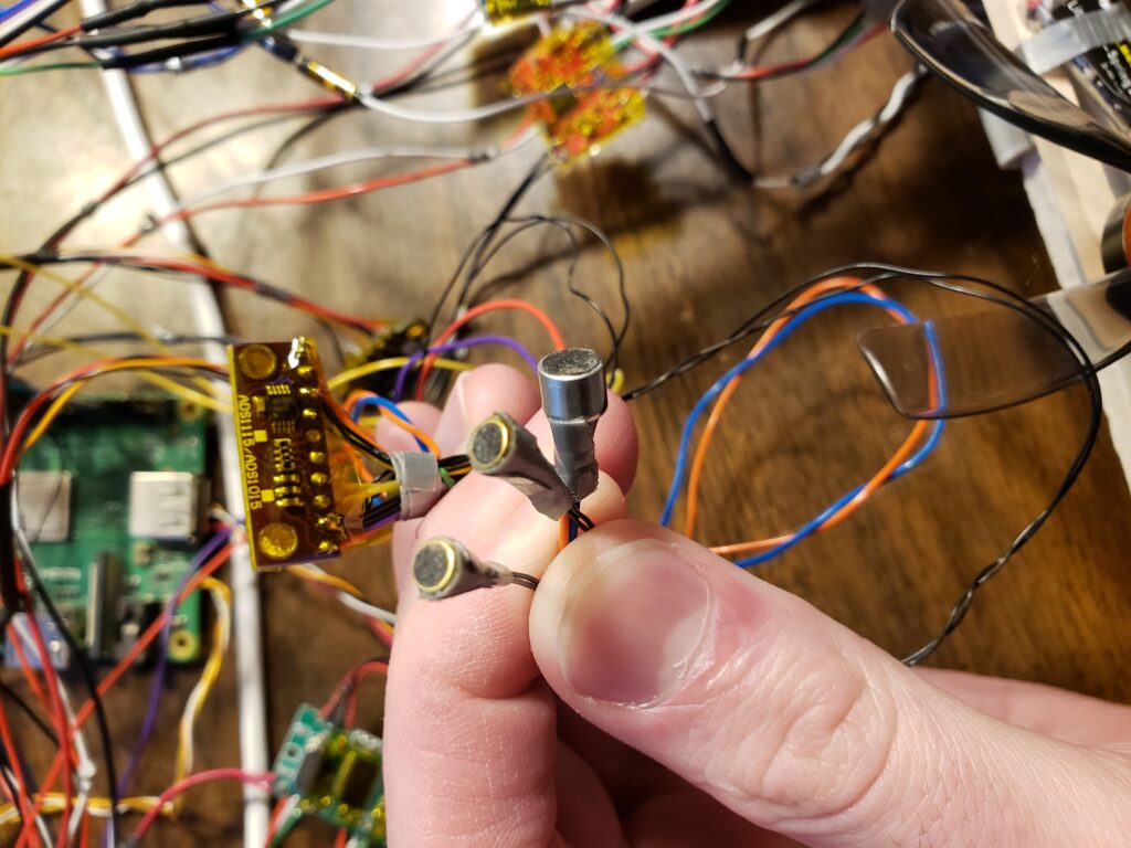
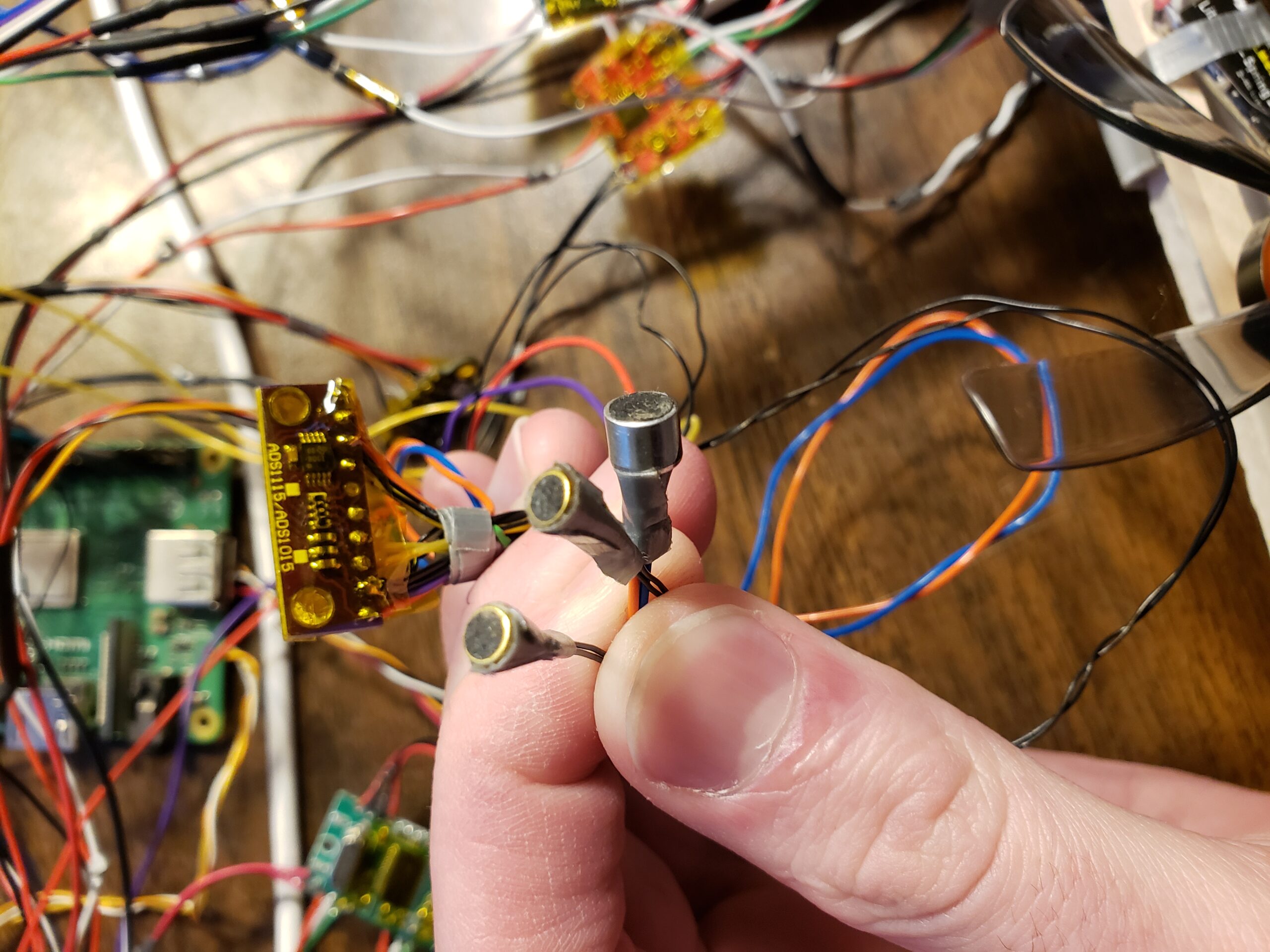
The ADC with direction sensing microphones
Wiring Design Changes
Voice input is my main method of control so I need to make sure my microphone is up to the task
I tired denoising the microphone output to improve the audio quality but I could never get it the way I wanted. The small USB microphones I choose were easy to fit into the project but their output was noisy and their range was short. I tired out two different microphone elements but it didn’t help with quality. My professor recommended using a condenser microphone instead as they are omnidirectional and produce better audio.
I’m going to switch to a single condenser microphone and use microphones on the ADC to turn the tile toward the speaker. The two smaller microphones will be mounted on either side of the tile and the larger microphone will be on the back. This way I can always turn the tile toward the speaker so the condenser microphone has the best quality.
Control Surface Assembly
Finally breaking out the balsa!
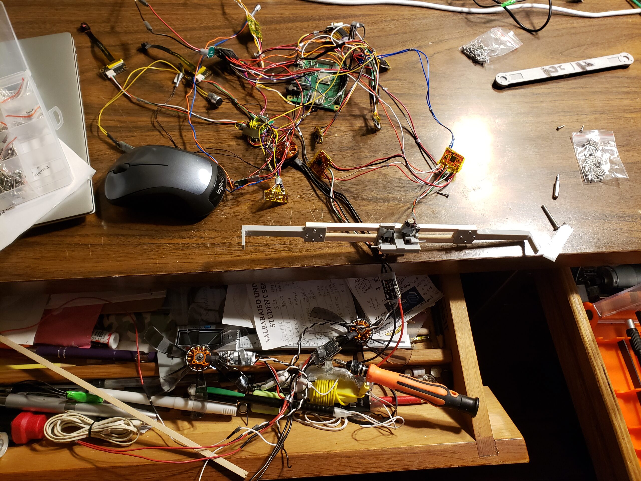
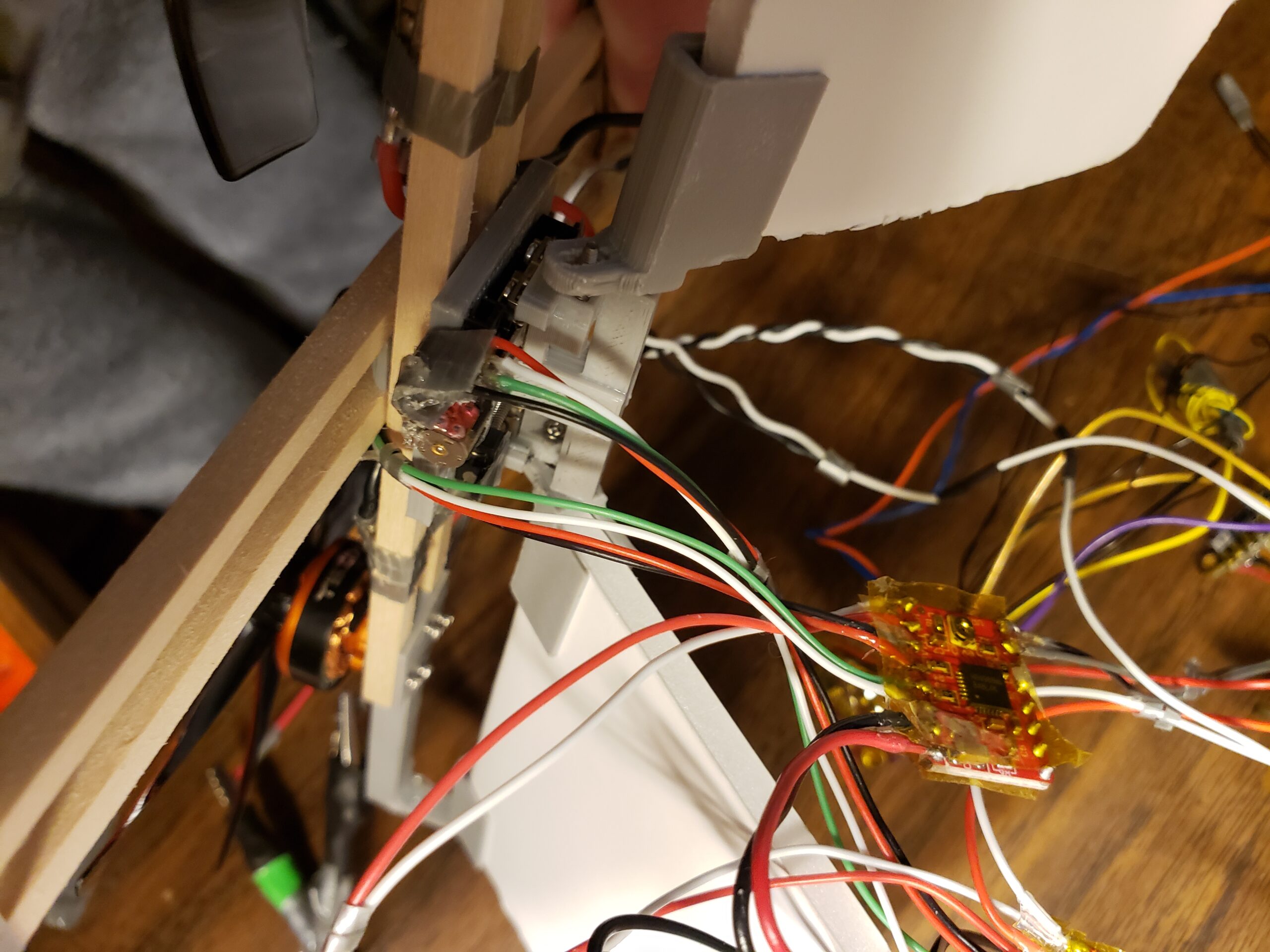
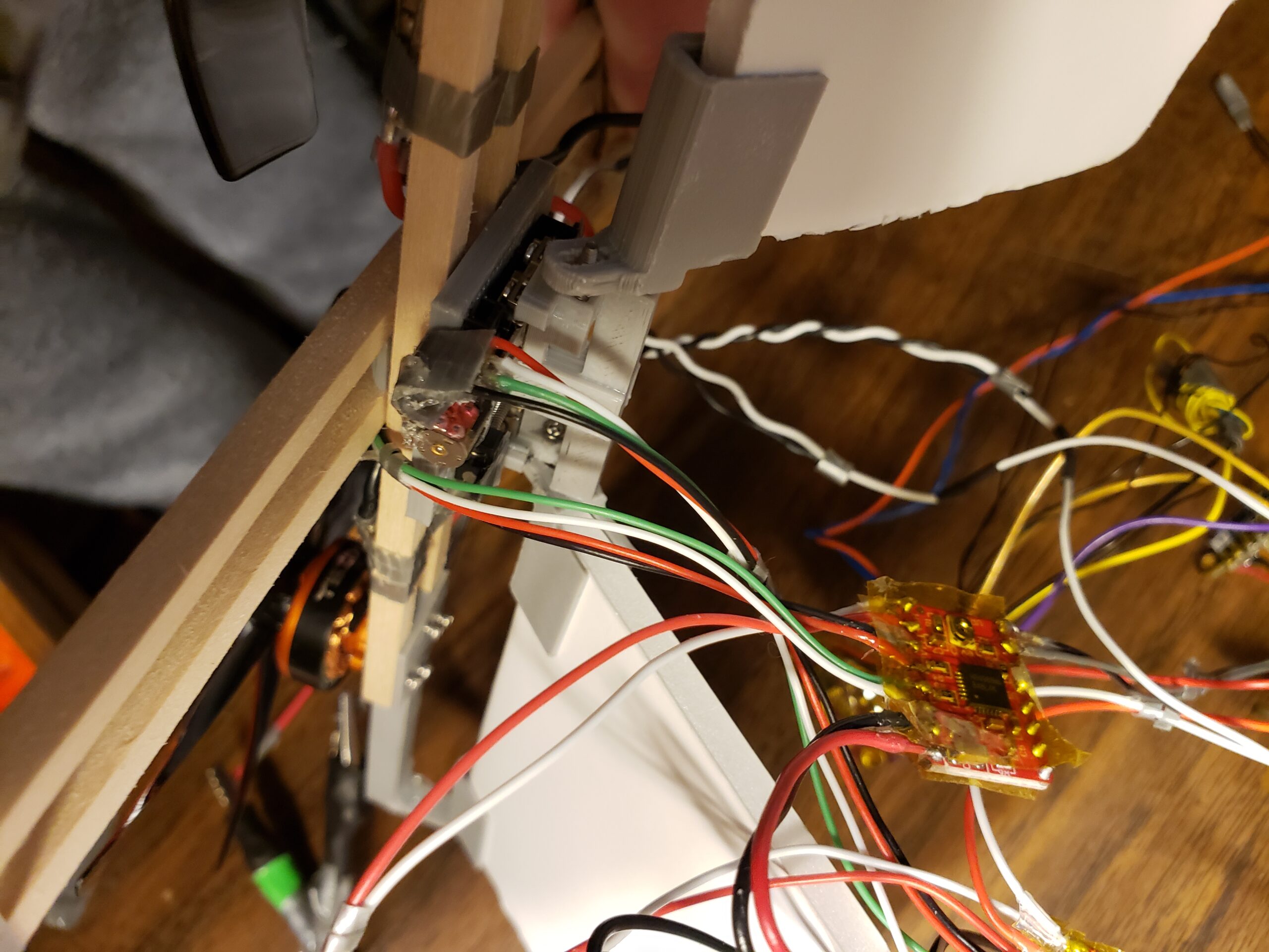
I was hoping to get a demo together for this post but building the control assembly took too much time. I’ll need to redesign these parts as the tolerances are too large but I rigged it together for a short test. The steppers work to turn the flaps but there isn’t much torque. I can increase the current from the driver but the steppers quickly heat up. This will be less of an issue when the props are running though. The flaps are designed to go all the way to 45 deg but I’m sure it won’t need to turn that quickly.
I tried to use the mpu6050 to read the yaw (heading) angle but found that this was more difficult. I would need a magnetometer to accurately read the yaw but I can estimate it biased of the acceleration data. It shouldn’t be too necessary as I’ll just use data from the two microphones to change the heading.
Next Steps
I’d like to avoid a repeat of this week so I’ll try to take things one step at a time
I really tried to do everything this week and ended up not having much to show. I have a lot of homework due next week so I’ll have less time to put toward the project. I’ll do my best but I definitely need to avoid staying up too late. I just really want to have something to show for the presentation in April.
Next week my plan is to:
Correct the CAD model and print the second iteration.
Assemble the corrected parts on a testbench
Program the stepper motors to set yaw based on the input from the microphones
I’m still waiting on server parts but that needs to be started as soon as possible