I had to design, build and program this arm in 5 days for a final
This arm is a little rough around the edges and I plan to continue improving it. I want to add encoders for reading motor positions and clean up the CAD. Currently the arm uses shunt resistors to tell when the arm is at an end stop. I’ll measure a larger voltage drop across the resistor when the motor is stalled so this was my cheap way of protecting the arm. I felt that this wasn’t bad for a five day design. The programming and electrical took up most of my time.
I designed the arm to require no adhesive (except for some cable management) so it was easy to build. The total BOM for this arm, including all the motors and microcontroller, comes in at $8. I’ll eventually lead a class where students will get to build arms like these.
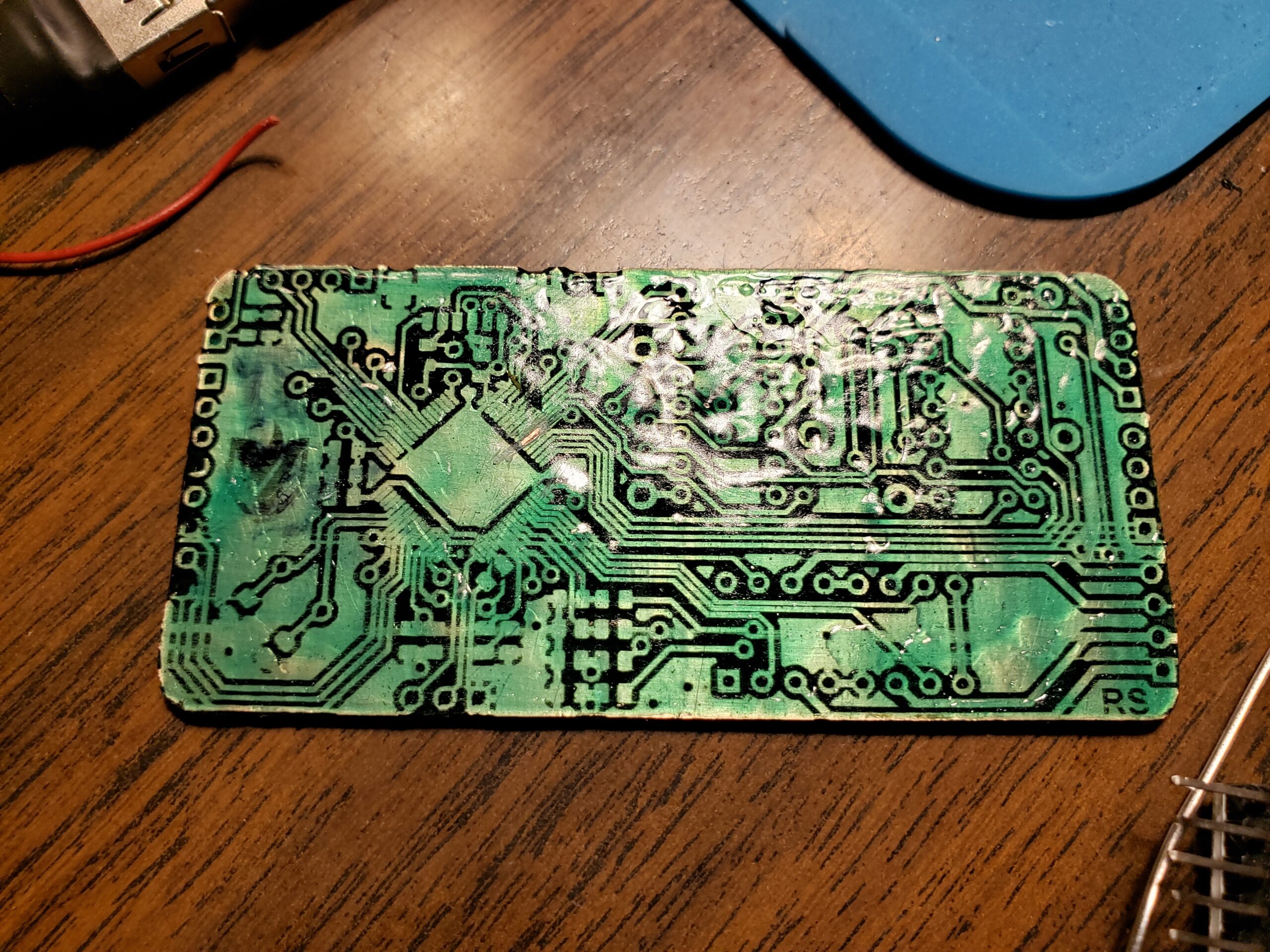
My First STM32 Board
I designed an Arduino board last year and this was very similar
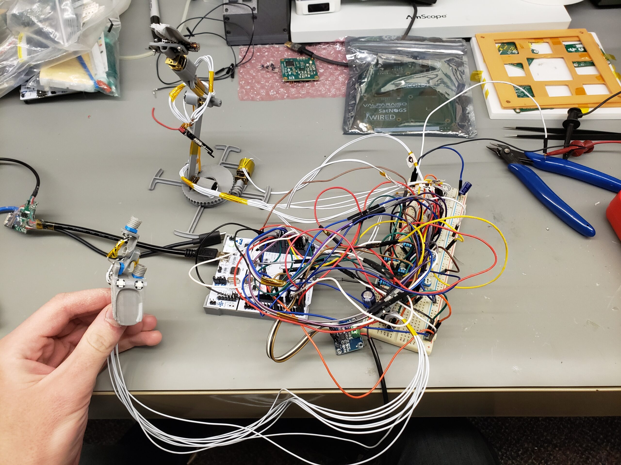
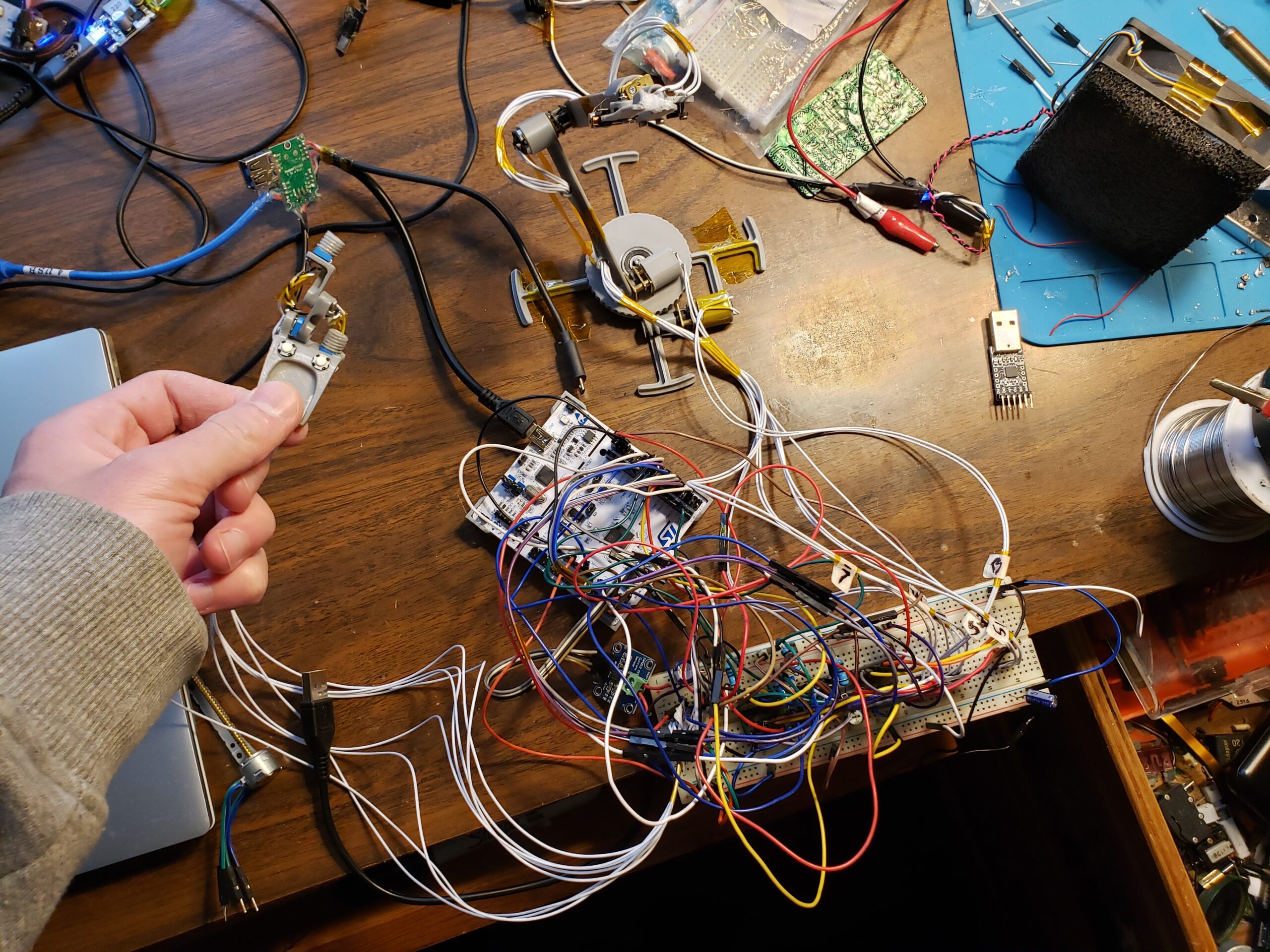
It’s a simple board because I didn’t have much time. I used large vias because I plan to make this on my school’s fiber laser. I was hoping I could get the board done for the demo but I couldn’t get into the lab that weekend. Instead I had to wire everything up on a breadboard which was a mess (image in the gallery). This board is simple and just uses three L293D dual h-bridges to drive the 4 DC motors and the claw stepper. I didn’t have enough pins to do differential measurement of the shunt resistors but the voltage drop should be enough for the 12bit ADC. The final design for the $8 arm will use an Arduino pro micro so I’ll need to rewrite the code and possibly switch out the shunts for potentiometers.
My Second Robot
A smaller stepper based arm that really could’ve used a PCB
I built this arm long before I knew how to make PCBs and the mega embed board I used wasn’t breadboard compatible. It has no sensors but the glue keeps everything together when it hits the end stops. The pot values are mapped to motor position and the arm has a “homing sequence” (by running all the motors into their end stops) so it starts in know position. This arm worked well enough but I wanted to build an arm that was more reproducible.
My Oldest Servo Based Arm
I learned to avoid cheap servos the hard way
This was my first major CAD project and I manually measured everything to draw sketches (in the project gallery). The spring allowed the lower servo to lift the arm. My partner and I programmed an Arduino to record and playback movements and accept input from my custom controller. I funded the project myself and made the mistake of buying knockoff MG996R servos. They had plastic gears that couldn’t hold up the weight of the arm. I recently got some proper servos to repair it and possibly experiment with AI control.
A Rushed Controller Design
I wanted an intuitive way to control the arm
I had one night to get this controller built and the arm programmed so it came out a little rough. It does make controlling the arm much easier and it includes buttons for the record/playback mode.